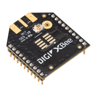
XBIB-C development boards Interface with the XBIB-C-GPS module
Digi XBee® 3 RF Module Hardware Reference Manual
66
I
2
C communication
There are two I2C lines connected to the host board through the 40-pin header, SCL and SDA. I2C
communication is performed over an I2C-compliant Display Data Channel. The XBIB-C-GPS module
operates in slave mode. The maximum frequency of the SCL line is 400 kHz. To access data through
the I2C lines, the data must be queried by the connected XBee 3 RF Module.
For more information about I2C Operation see the I2C section of the Digi Micro Python Programming
Guide.
For more information on the operation of the XBIB-C-GPS board see the CAM-M8 datasheet. Other
CAM-M8 documentation is located here.
UART communication
There are two UART pins connected from the XBIB-C-GPS to the host board by the 40-pin header: RX
and TX. By default, the UART on the XBIB-C-GPS board is active and sends GPS readings to the
connected device’s secondary UART pins. Readings are transmitted once every second. The baud rate
of the UART is 9600 baud.
For more information about using Micro Python to communicate to the XBIB-C-GPS module, see Class
UART.

 Loading...