Pin signals Pin signals for the XBee 3 through-hole module
Digi XBee® 3 RF Module Hardware Reference Manual
29
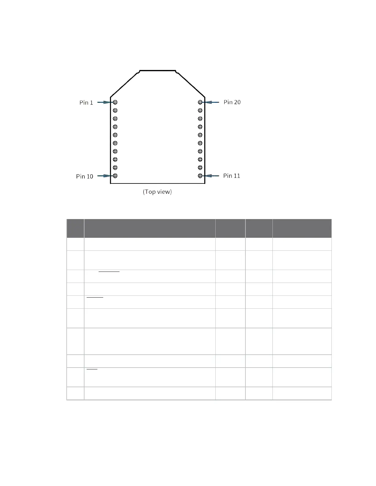
Pin signals for the XBee 3 through-hole module
The following drawing shows the through-hole pin locations.
The following table shows the pin signals and their descriptions for the XBee 3 though-hole device.
Pin# Name Direction
Default
state Description
1
VCC - - Power supply.
2
DOUT/DIO13 Both Output UART data
out/GPIO.
3 DIN/CONFIG/DIO14
Both Intput UART data in/GPIO.
4
DIO12/SPI_MISO Both - GPIO/SPI data out.
5 RESET Input
- Device reset.
6
RSSI PWM/DIO10 Both Output RX signal Indicator
strength/GPIO.
7
PWM1/DIO11/I2C SDA Both Disabled Pulse width
modulator/GPIO/I2C
SDA.
8
[reserved] - Disabled Do not connect.
9 DTR/SLEEP_RQ/DIO8
Both Input Pin sleep control
Line/GPIO.
10
GND - - Ground.

 Loading...


