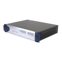
96 I/O Guide
4
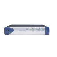
Sync Mode LEDs
The SYNC MODE LEDs indicate different clock
source modes. Synchronization mode LEDs re-
flect the Clock Source choice in Pro Tools.
Only one HD I/O can be Loop Master at a time.
When you change the clock source to an exter-
nal clock on a particular HD I/O, that HD I/O
will automatically become the Loop Master and
all other HD I/Os in the chain will be switched
to Loop Slave mode. The Loop Master LED will
be continuously lit on the current Loop Master
peripheral only, and unlit on all other peripher-
als.
For more information, see “Synchronization
Mode and Clock Source” on page 19.
Meters
These four-segment LEDs indicate signal level
for each of 16 channels. Two additional LEDs,
located to the left of the meters, indicate
whether the 96 I/O is displaying input or output
levels; the meters indicate output levels by de-
fault, and can be switched from within the
Hardware Setup dialog in Pro Tools.
These meters are calibrated at –42 dB, –18 dB, –6
dB, and 0 dB, respectively. Note that 0 dB is not
to be confused with clipping; please use the on-
screen meters in Pro Tools to determine whether
a signal is clipping. See the
Getting Started with
HD Guide
.