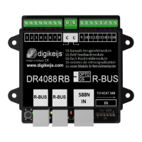
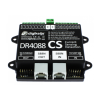
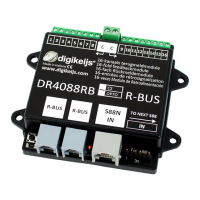
The Digikeijs DR4088RB-xx is a versatile feedback module designed for model railway control systems, connecting to the central control panel via the R-Bus®. This module offers 16 feedback inputs, making it suitable for monitoring various track sections or sensors. It is available in two main versions: the CS version (Current Sensor) for 2-wire track systems and the OPTO version for connecting reed contacts or 3-wire track signals to track ground.
Function Description
The primary function of the DR4088RB-xx is to provide feedback from the model railway layout to the central control unit. This feedback is crucial for automated operations, track occupancy detection, and precise train control. The module translates signals from track sections or sensors into digital information that the control system can interpret.
The R-Bus® is a key interface for this module, designed to handle a significant number of feedback modules. The R-Bus® is always divided into two lines, with the first string starting at module address 1 and the second at module address 11. A maximum of 160 feedback modules can be added to the R-Bus®. Each module is considered to consist of 8 feedback units, even though the DR4088RB-xx itself contains 16 feedback inputs. Therefore, the first DR4088RB-xx is assigned module addresses 1 and 2, the second module addresses 3 and 4, and so on.
Important Technical Specifications
The DR4088RB-xx is designed with robust connection terminals. The 16 feedback input terminals are suitable for a cross-section of 0.5mm², while the two common "C" terminals are designed for a larger cross-section of 0.75mm².
For the DR4088CS (Current Sensor) version:
- Number of inputs: 2 x 8 (total 16)
- Suitable for: 2 conductors
- Minimum load for safe reporting: 2 mA
- Max. load per contact: 2 A
- Max. load capacity per contact for max. 100 ms: 5 A
- Peak load for 8 feedbacks at "C" total: 6 A
For the DR4088OPTO (Opto-isolated) version:
- Number of inputs: 2 x 8 (total 16)
- Suitable for: 3 conductors when using the DR50xx (for Hall sensors, reed contacts, or track signals)
- Minimum load for safe reporting: Not specified (as it's opto-isolated, current sensing is not the primary mechanism)
- Max. load per contact: Not specified (as it's opto-isolated, it typically handles voltage signals)
- Max. load capacity per contact for max. 100 ms: Not specified
- Peak load for 8 feedbacks at "C" total: Not specified
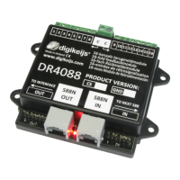
Hardware Overview
The module features several key components:
- Connection feedback 1 to 8: Terminals for the first eight feedback inputs.
- Common connection "C": For the right or left detector group, serving as a common return path for feedback signals.
- Connection feedback 9 to 16: Terminals for the remaining eight feedback inputs.
- Programming button: Used to initiate the programming process.
- Green LED: Indicates power supply availability and signals different programming levels through various flashing cycles.
- R-Bus® connection (x2): For connecting the module to the R-Bus® network.
- Yellow LED: Flashes during activity on the R-Bus®.
- Red LED: Flashes during load or activity at the S88N connection.
- S88N In connection: For connecting to an S88N bus.
- S88 In connection: For connecting to an S88 bus.
Usage Features
The DR4088RB-xx offers flexible programming options, both with and without additional DR4088 modules connected via the S88N port.
Programming without additional DR4088 on the S88N port:
The module needs to be assigned a module address (e.g., 1, 3, 5, 7, etc.) and informed that it consists of 2 x 8 feedbacks.
- Using the DR5000: The DR5000 Tool's "XN-FB Bus" properties allow for programming via the "FB Call Programming Module" wizard. Users follow on-screen instructions to set the module address and specify that the module represents 2 feedback units (i.e., 16 inputs).
- Using the Z21® and Maintenance Tool: This method involves a sequence of button presses on the DR4088RB-xx and actions in the Maintenance Tool. First, the programming button is pressed once, causing the green LED to flash. Then, module address 1 (or 3, 5, 7, etc.) is sent via the Maintenance Tool. After confirmation, the green LED flashes as before. A quick double-press of the programming button changes the green LED's flashing rate, indicating readiness to set the number of modules. Module address 2 is then sent via the Maintenance Tool to confirm that the module consists of 2 x 8 feedbacks.
Programming with additional DR4088 on the S88N connection:
When multiple DR4088 modules are daisy-chained via the S88N connection, the number of modules to be programmed increases. For example, if one additional DR4088xx is connected, the number of modules increases from 2 to 4. A maximum of four DR4088xx can be connected to the S88 connection on each R-Bus® string, meaning a single DR4088RB-xx can manage up to 10 feedback modules (10 x 8 feedbacks = 80 inputs) on an R-Bus® string. If a second R-Bus® line is set up (starting at module address 11), it can also manage up to 80 feedback modules.
- Using the DR5000: Similar to the single module programming, the DR5000 Tool is used. The key difference is that the number of modules will be set to 4 (for one additional DR4088xx) or 10 (for four additional DR4088xx) during the programming process. An important note for LN or RB module users is to set the ext88N IN number of 16 and 8 input modules to 0 on the DR5000, which can be verified by checking if feedback monitor rows 1 and 9 are white with blue, not red.
- Using the Z21® and Maintenance Tool: The initial steps are the same as for single module programming (press button once, send module address 1). Then, after the double-press of the programming button, the module address 4, 6, 8, or 10 is sent via the Maintenance Tool, depending on the total number of available modules in the S88N chain.
Connection Examples
The manual provides several connection examples to illustrate the versatility of the DR4088RB-xx:
- DR4088RB-CS; 2-wire track: Shows how multiple DR4088RB-CS modules are connected to a DR5000 central unit via the R-Bus® for current detection on 2-wire tracks.
- DR4088RB-CS and DR5033 Booster 2-wire track: Demonstrates integrating DR4088RB-CS modules with a DR5033 booster in a 2-wire track system, including track isolation for booster sections.
- DR4088RB-OPTO; Hall sensors, 3-wire track: Illustrates connecting Hall sensors (or light barriers, reed contacts) to the DR4088RB-OPTO module for 3-wire track systems, with the sensors powered by an external 5V-20V DC/AC supply and providing feedback to the module.
- DR4088RB-OPTO; switch track, 2-wire track: Shows how reed contacts, push buttons, or switches can be connected to the DR4088RB-OPTO module for feedback in a 2-wire track system, again with external power for the sensors.
Maintenance Features
The DR4088RB-xx does not have a function for resetting to factory settings. This is deemed unnecessary because the only configurable functions are the module address and the number of modules. To "reset" the module address to the basic setting 1, it is sufficient to re-send module address 1 to the DR4088RB-xx as described in the programming section. To reset the number of modules, simply re-send the value "2" (for 2 x 8 feedbacks) to the DR4088RB-xx. No further steps are required for maintenance or resetting.
All Digikeijs products come with a 24-month manufacturer's warranty. It is crucial to read and follow the operating instructions carefully, as damage caused by non-compliance will invalidate the warranty. Opening the product housing also voids the warranty. Digikeijs reserves the right to make technical or other changes, as well as changes in product availability, hardware, firmware, and software without prior notice. All operating instructions and other written materials are protected by copyright, and reproduction is not permitted without written permission from Digikeijs.