Do you have a question about the Digikeijs DR5013 DIGIREVERSE and is the answer not in the manual?
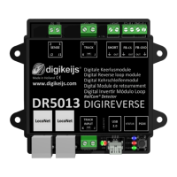
Provides an overview of the DR5013 module and its capabilities.
Details the manufacturer's warranty terms and conditions for the product.
Outlines legal notices, copyright, and disclaimers regarding the manual and product.
Describes the DR5013's functionality, including operation modes and key features.
Lists the technical details, such as terminal cross-section and load capacity.
Details the physical components and connections of the DR5013 module.
Explains the prerequisites and system requirements for configuring the DR5013.
Guides users on where and how to download the necessary configuration software.
Provides step-by-step instructions for installing the DR5013 configuration software.
Explains how to establish a USB connection between the DR5013 and a PC for configuration.
Offers a visual guide to the different sections of the configuration software interface.
Details the functionalities available through the USB connection, like firmware updates.
Instructs on how to reset the DR5013 module to its default factory settings.
Guides on the process of updating the device's software and firmware for improved performance.
Lists the different firmware versions released for the DR5013 module.
Explains how to utilize and configure LocoNet® features for feedback and reporting.
Covers the general properties and settings for the DR5013 module.
Details specific module properties related to Digitrax specifications and Railcom®.
Introduces DR Script for programming complex processes and controlling the module.
Explains how to configure properties for sensor tracks and feedback numbers.
Details the configuration of the Global Detector for track direction and occupancy.
Shows a wiring example for using the DR5013 with short-circuit detection.
Illustrates connecting the DR5013 with short-circuit detection and LocoNet®.
Demonstrates connecting the DR5013 with multiple sensor tracks and LocoNet®.
Shows a wiring example using sensor tracks S1, S2, and LocoNet®.
Illustrates connecting the DR5013 with sensor tracks S1, S2, but without LocoNet®.
Explains how to connect external feedback outputs from the DR5013.
| Manufacturer | Digikeijs |
|---|---|
| Product Number | DR5013 |
| Category | Control Unit |
| Compatibility | DCC |
| Number of Outputs | 2 |
| Control Interface | DCC |
| Function | DIGIREVERSE - Digital Reverse Loop Module |