DR5013 DIGIREVERSE
P 32
www.digikeijs.com
® R-Bus, B-Bus are trademarks which are registered in the name of Modelleisenbahn GmbH. XpressNet and RS-Bus is a trademark registered in the name of Lenz
Stand 2021-07-06
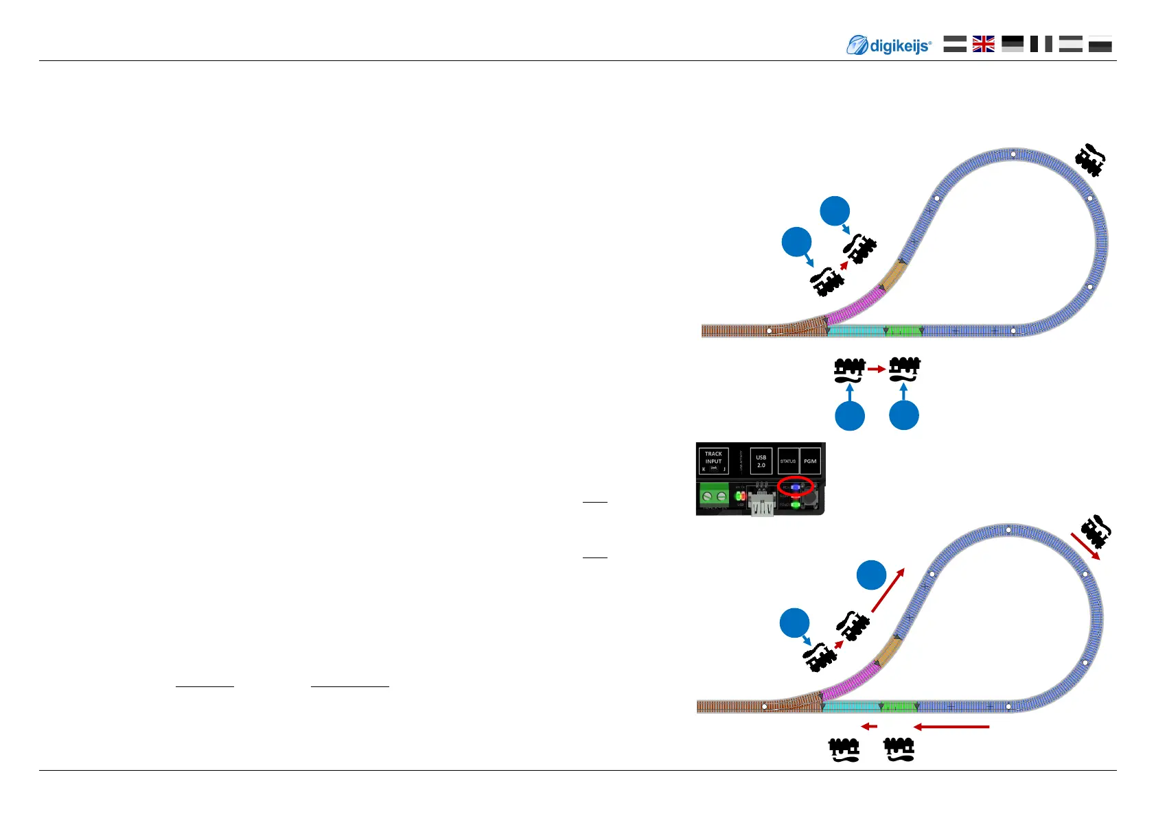
DR5013 Check connecon:
This allows you to test whether S0, S1, S2 and S3 have been wired correctly:
1) Switch o track voltage.
2) Remove all locomoves and other loads from the sensor tracks (S0, S1, S2, S3).
3) Switch on track voltage.
4) Place the locomove on the sensor track S0 and observe whether the blue LED lights up.
If the blue LED does not light up, check the wiring or the address assignment in the app of
S0!
5) Remove locomove from sensor track S0.
6) Place the locomove on the sensor track S1 and observe whether the blue LED lights up.
If the blue LED does not light up, check wiring of S1!
7) If both tests (4. & 6.) show that the blue LED is lit, the sensor tracks S0 and S1 are wired cor-
rectly.
The next step is to perform the funcon test with the sensor tracks S2 and S3.
can be carried out.
8) Place the locomove on the sensor track S3 and observe whether the blue LED is not illumi-
nated. If the blue LED lights up, check the wiring or the address assignment in the app of S3!
9) Remove the locomove from the S3 sensor track.
10) Place the locomove on the sensor track S2 and observe whether the blue LED is not illumi-
nated. If the blue LED lights up, check the wiring of S2!
11) If both tests (9. & 10.) show that the blue LED is not lit, the sensor tracks S3 and S2 on the
DR5013 are wired correctly.
12) At the end of the test series, place the locomove on the sensor track S0 and drive in direc-
on S1 over the double track separaon point into the reversing loop track (T).
If the blue LED does not light up or a short circuit is triggered at the DR5013, the track con-
necons at the track input of the DR5013 must be replaced.
13) Finally go through the complete reversing loop again to test the connecon completely: S0 ->
S1 -> T -> S2 -> S3
6.1 Commissioning instrucons DR5013 with sensor tracks S0,S1,S2,S3 (without connecon to PC)
To check the connecon of the DR5013 without a USB connecon to the PC, use this procedure. This can be used to test if the wiring is correct and there is no
error.
S0
S1
S3 S2
Blue LED Indicaon of polarity of the
reversing loop track
S0
S1
S2 S3
4
6
8
10
12
13
 Loading...