DG-GS4200 Installation Guide
1-3
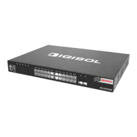
1.3.2 Back Panel
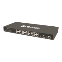
The back panel of DG-GS4228 is shown below, and there is 1 220V AC power socket
and 1 grounding screw.
Fig 1-5 Back Panel of DG-GS4228
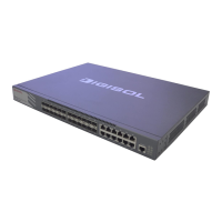
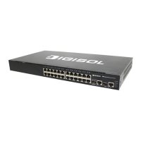
The back panel of DG-GS4228P is shown below, and there is 1 220V AC power
socket and 1 grounding screw.
Fig 1-6 Back Panel of DG-GS4228P
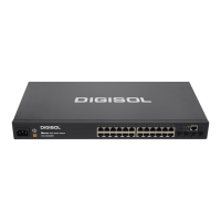
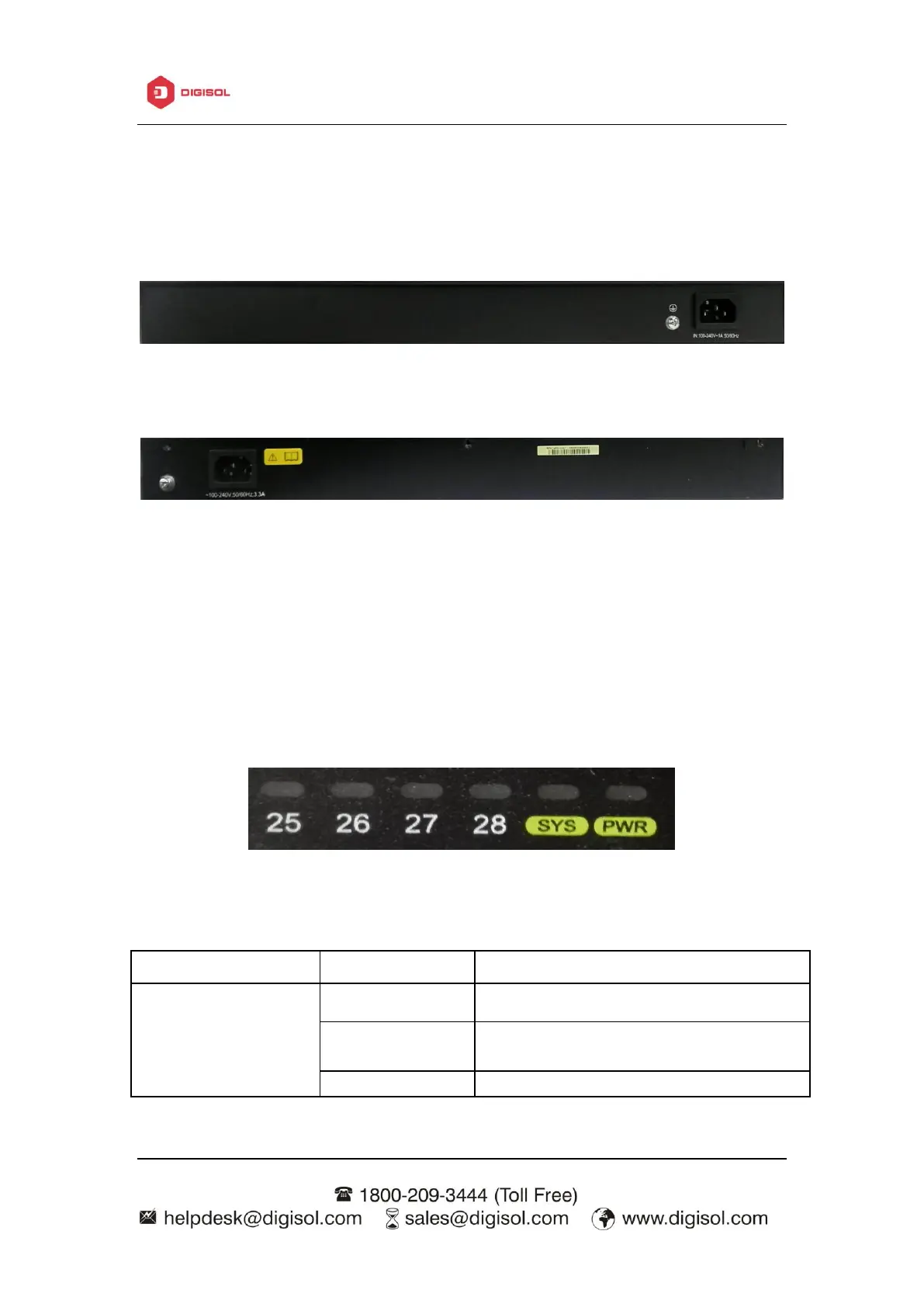
1.3.3 Status LEDs
DG-GS4200 series switches include port indicator and system status indicator, as
shown in below and described in the following table.
1.3.3.1 Port Indicator Description
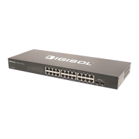
Fig 1-7 DG-GS4228 LED diagram
The port is linked successfully
The port is linked successfully, and
receive/send data
 Loading...