8
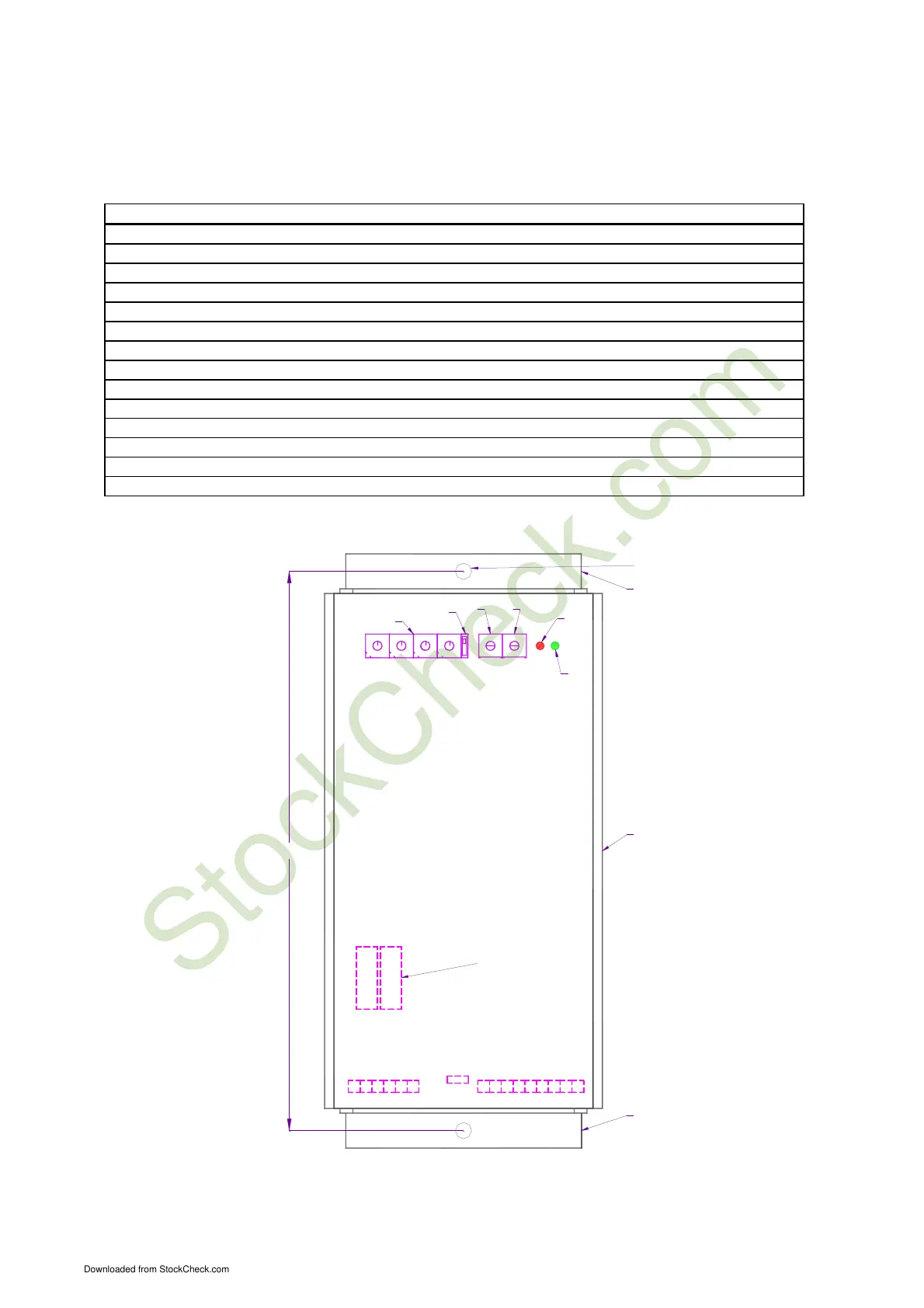
PARTS
IDENTIFICATION:
PART REF. FUNCTION
Connector
M3 Mains input 230Vac and Load output,
Connector
M2 Start-stop command and Remote potentiometer
Fuses
F1 Mains fuses
Trimmer
P1 Sets minimum reference voltage from potentiometer
Trimmer
P2 Sets maximum reference voltage from potentiometer
Rotary switches
SW1 Selects output frequency
Switch
SW2 Sets start command (autostart or external start command)
Jumper
H4 Selects start command (PNP or NPN)
Green led
DL1 Power supply running (internal or external start command received)
Red led
DL2 Power supply inhibited
Box
X1 Anodized aluminum
Lower bracket
X4 Lower bracket anodized aluminum
Hole
X5 Fixing box to wall
Upper bracket
X6 Upper bracket anodized aluminum
0
F1
X1
X4
X6
X5
SW1
SW2
P2
DL2
DL1
P1
9
8
7
6
5
4
3
2
1
4
1
2
3
6
9
8
7
5
0
4
1
2
3
1
4
3
2
9
0
8
6
5
0
9
8
7
5
6
7
H4
239.0
M3 M2−M4
6 5
4
3
2 1
9 8
7
6 5
4
3
2 1
C = hundreds
D
U DecC
D = tens
Dec = tenth
U = Unit
Downloaded from StockCheck.com