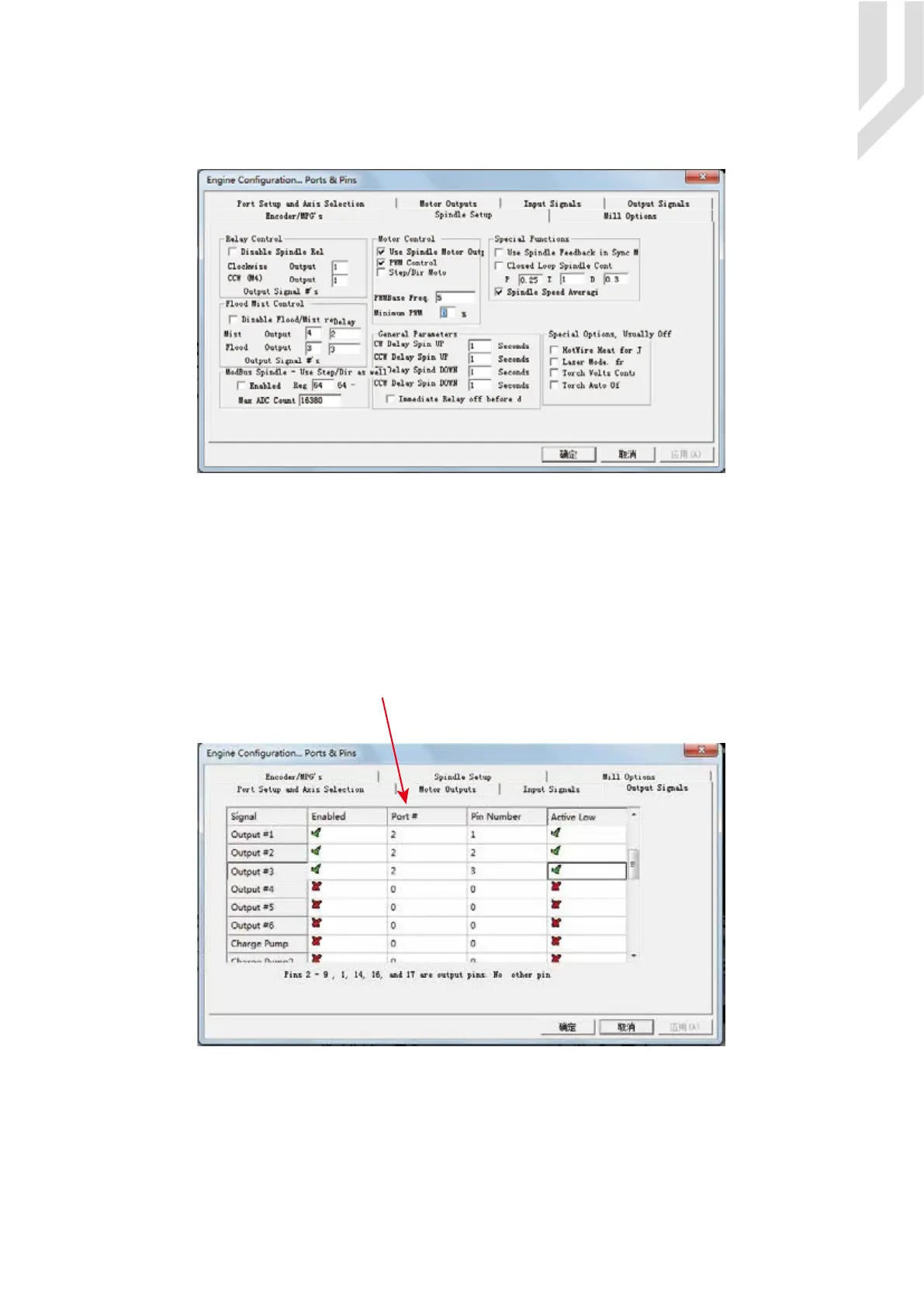
Here we can configure the spindle rotates CW、Reverse CCW、Mist、Flood pin,.They have been
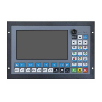
configured as 1、2、3、4. Corresponding to output#1~output#4 in Figure4-11.output#1~output#6 in Output
Signal Setup dialog can be Configured into these 4 signals. Here we only configure CW/MIST/FLOOD. CW
is controlled by OUT1. MIST is controlled by OUT2. Flood is controlled by OUT3. Here we note correspon-
dence between 2 page. Please select “use spindle motor output” if required PWM speed spindle. And select “
PWM Control”. Our PWM pin fixedly arranged on a special pin on Stepper motor setting dialog.
Here by our controller we already define all the Output Ports to Port No. 2.
Click “Spindle Setup” switch to the spindle settings page.
Spindle setting corresponds to the output configuration
Page -21Digital Dream Mach3 Motion Controller EC500 User’s Manual
All Output Ports are defined to Port No. 2.


 To Next Page