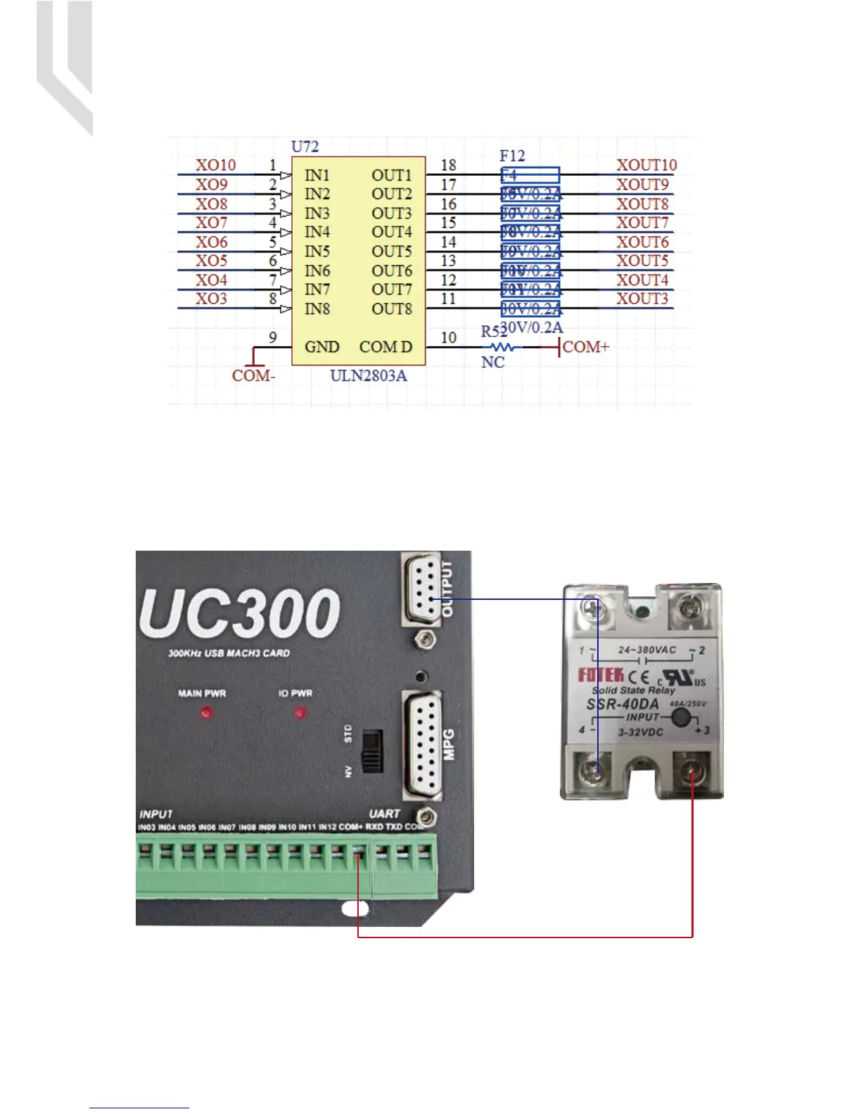
Picture 5-6 OUTPUT port internal structure
Picture 5-7 Solid Replay Connection
The general output interface has a built-in relay drive circuit, which can be directly connected to less than the
100mA relay. Reference Picture 5-6 for wiring with relay, using output 4(Pin No.2) and COM+.By the connec-
tion method of Picture 5-6,it is the controller supply the power for the Output Ports.If the users want to supply
the external power for the relay,then the connection is between GND(Pin1) and Output4(Pin2).
GND is COM-.
UC300 User’s ManualPage 8Digital Dream Mach3 Motion Controller
OUT4
COM+

 Loading...


