5.1 USB Communication Port to PC
To setup the connection between the controller and the Mach3 software on computer,UC300 use the USB
port,as the Marked No.1 on Picture 5-1.
UC300 User’s ManualPage 5Digital Dream Mach3 Motion Controller
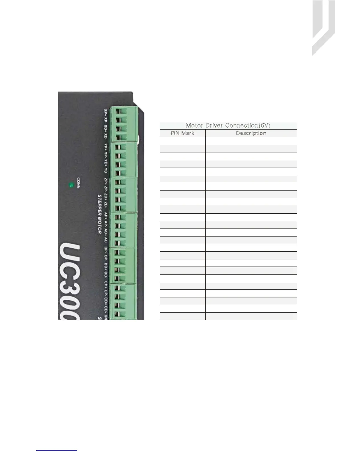
5.2 Stepper/Servo Motor Control Interface Connection
Picture 5-2 UC300 Stepper/Servo Mark and description
PIN Mark Description
XP+
XP-
XD+
XD-
YP+
YP-
YD+
YD-
ZP+
ZP-
ZD+
ZD-
X Axis Direction Output -
X Axis Direction Output +
X Axis Pulse Output -
X Axis Pulse Output +
Y Axis Direction Output -
Y Axis Direction Output +
Y Axis Pulse Output -
Y Axis Pulse Output +
Z Axis Direction Output -
Z Axis Direction Output +
Z Axis Pulse Output -
Z Axis Pulse Output +
AP+
AP-
AD+
AD- A Axis Direction Output -
A Axis Direction Output +
A Axis Pulse Output -
A Axis Pulse Output +
BP+
BP-
BD+
BD- X Axis Direction Output -
B Axis Direction Output +
B Axis Pulse Output -
B Axis Pulse Output +
CP+
CP-
CD+
CD-
Motor Driver Connection(5V)
B Axis Direction Output -
C Axis Direction Output +
C Axis Pulse Output -
C Axis Pulse Output +
C Axis Direction Output -
As the Marked No. 2 from Picture 5-2,there is the Stepper/Ser-
vo Interface.The device can be used to control machine tools
with stepper or servo motor controls with pulse and direction
signals.The option for users is 3-6 axis.

 Loading...


