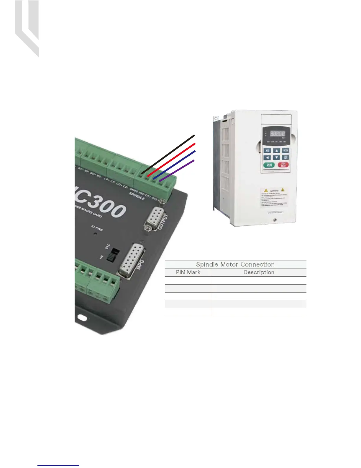
As Picture 5-1 showed,No.3 terminal block is for Spindle control output. We define the interface from left are
GNDs,VSO,OUT1,OUT2,Index. They are Ground of output, Speed adjusting voltage,Digital output1, Digital
output2, Spindle speed feedback input.
Take Nowforeuer inverter as the example. Spindle control output and the inverter connection showed as
Picture 5-6.X1 control spindle Clockwise RUN and STOP, AIN1 modify spindle's speed. if we need to control
spindle anti-clockwise RUN and STOP, we need to connect X2 to OUT2.
5.3 Spindle Control Output Port
Picture 5-3 EC500 Spindle Control Setup
COM
AIN1
X1
X2
VSO connects to Speed adjustment which defined by voltage 0-10V.
The relationship Max. Spindle speed and current spindle speed is as below:
VSO(Output Voltage)=10*current spindle speed(S)/Maximum Spindle Speed(Max.S).
For example if we set the Max Speed is 24000,and we need the current spindle speed is 18000,then
VSO=10*18000/24000=7.5V.
The following picture 5-7 is the setting method of Max. speed in Mach3 software.
GNDs
VSO
INDEX
OT1
OT2
0-10V Speed adjustable output
Output Ground
Spindle speed feedback input
Common IO output1
Common IO output1
Spindle Motor Connection
PIN Mark Description
UC300 User’s ManualPage -6Digital Dream Mach3 Motion Controller

 Loading...


