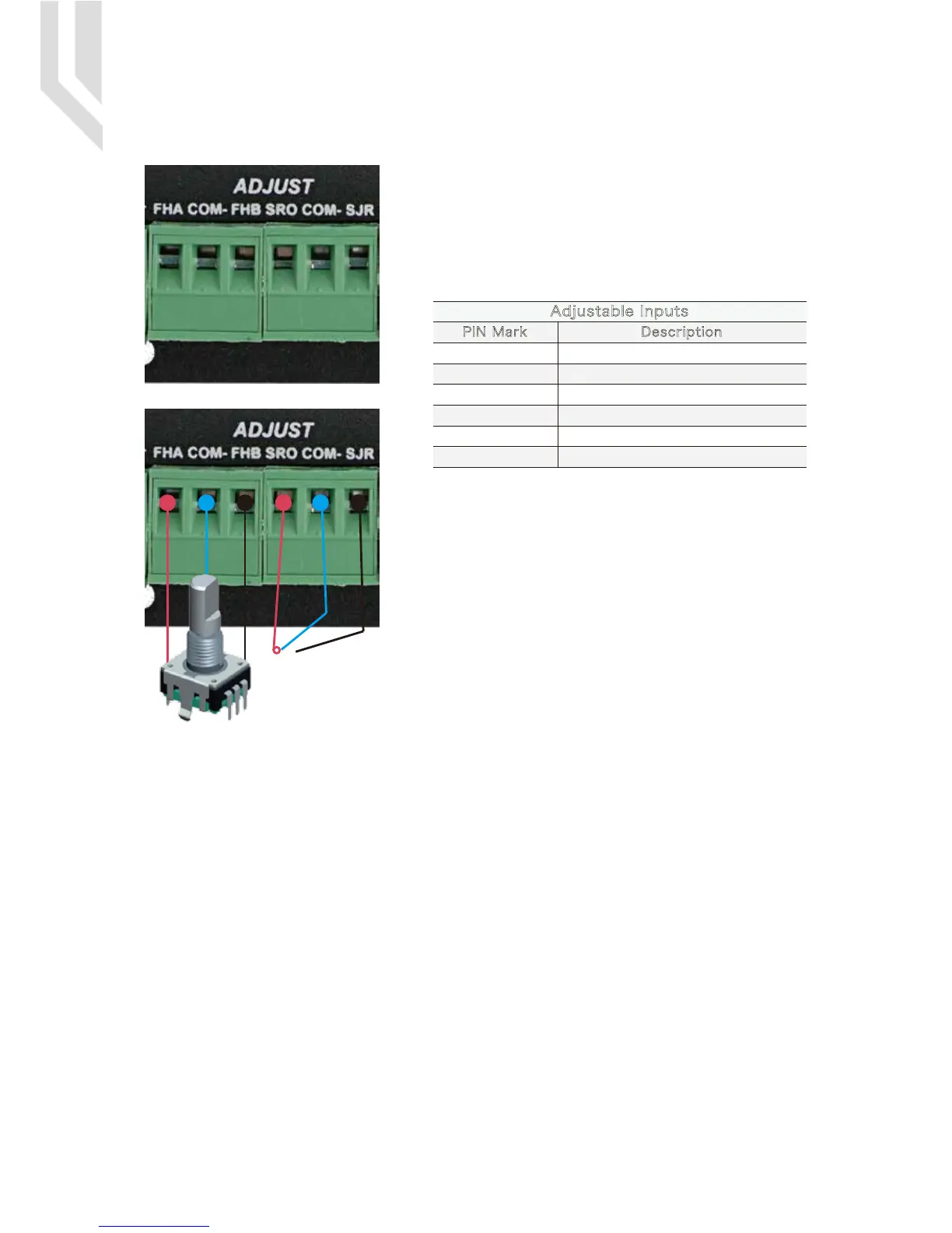
5.8 Adjustable Input Interface
From the Picture 5-1 shows,the Marked No. 9 is for adjustable
input interface,which must be operated by the digital potenti-
ometer.The interface will make us to operate the FRO,SRO
and SJR very Easy and convenient.The Interface should be
operated with position switch and digital potentiometer,for the
FRO,SRO and SJR adjustment.
If there is no connection between COM- and SRO or COM-
and SJR,the default is FRO Active,it means it is in the term of
‘Feed rate override’.When there is connection between COM-
and SRO,it is in the terms of ‘Spindle speed rate override’;if
there is connection between COM- and SJR,it is in the term of
‘Jog Mode’.
COM-
COM-
FHA
FHB
SRO
SJR Jogging Mode
Adjustable Inputs
PIN Mark Description
Potentiometer Phase A
Potentiometer Phase B
Spindle Speed Override
Comman Ground
Comman Ground
UC300 User’s ManualPage -12Digital Dream Mach3 Motion Controller

 Loading...


