ENGLISH
32
DESCRIPTION OF THE CONTROL UNIT
The CITY7 control unit is an innovative V2 product guaranteeing
safety and reliability for swing gate automation.
T
he CITY7 design has been aimed at creating a product which
adapts to suit all needs, thus obtaining an extremely versatile
control unit satisfying all the necessary requirements for a
functional and efficient installation.
• 230V - 50Hz or 120V - 60Hz power supplies, depending on
the model, for 2 single phase motors (700W global).
• Input for keyswitch or push-button.
• Input for safety photocell.
• Input for safety edge, capable of handling standard edges
with switch normally closed and conductive rubber edges with
nominal resistance of 8.2 kOhms.
• Pre-opening safety device testing.
• Dip-switch programmable operational logic.
• Adjustment of motor power and operation time by means of
a trimmer.
• Quick plug-in connector for inserting a Mr1 series receiver.
• LED monitoring of inputs.
• Courtesy light output.
• IP55 casing.
ADJUSTMENT OF THE POWER AND
OPERATIONAL TIMES
The power and operating times may be adjusted by means of 4
trimmers located on the control unit:
POWER: motor power.
WORK: motor operating time (2 - 120 seconds).
PLEASE NOTE: it is recommended that operating times be
set with the slow down function disabled (DIP 5 OFF).
WARNING: the adjustment of times has to be made
when the gate is still
PAUSE: pause time before automatic re-closure
(2 - 150 seconds).
DELAY: time delay between the two gate leaves
(0 - 90 seconds).
CONTROL UNIT INDICATORS (LEDS)
The highlighted boxes indicate the state of the LEDs when the
gate is resting.
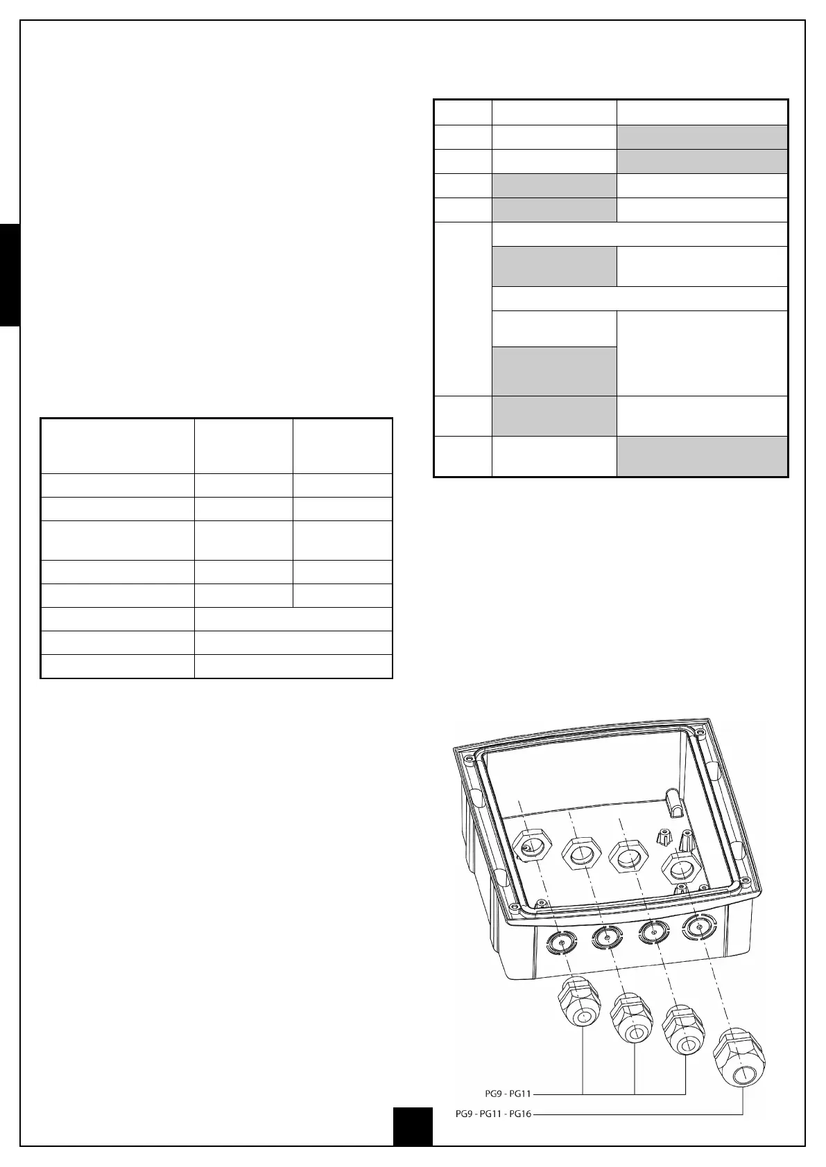
CABLE GLAND ASSEMBLY
The casing can accept 4 cable glands in the special easy-break
housings.
The type of cable gland is indicated in the figure.
PLEASE NOTE:
• Remove the electronic circuit board before drill the casing.
• Drill the container using a suitably sized cutter,
according to the dimensions of the cable gland.
• Fix the cable glands using the special nuts.
TECHNICAL
SPECIFICATIONS
230V models 120V models
Power supply 230V / 50Hz 120V / 60Hz
Max motors load 700W 700W
Max accessories load 24V 3W 3W
Working temperature -20 ÷ +60 °C -20 ÷ +60 °C
Protection fuse F1 = 5A delayed F1 = 8A delayed
Dimensions 170 x 185 x 70 mm
Weight 800 g
Protection IP55
LED ON OFF
START START input closed START input open
IN2 START P. input closed START P. input open
STOP STOP input closed STOP input open
PHOTO PHOTO input closed PHOTO input open
EDGE
Standard edge
E
DGE input closed
(edge not pressed)
E
DGE input open (edge
pressed)
Resistive rubber edge
EDGE input closed
(edge pressed)
EDGE input open
(fault)
Edge NO pressed:
8K2 between EDGE
input and common (-)
mains
Control unit
powered-up
Control unit NOT powered-up
overload
Accessory power
supply overload
Accessory power supply within
normal operational limits