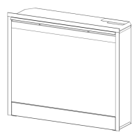
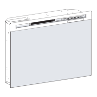
Partially
Reective
Glass
Retaining
Clip
Figure 7
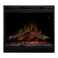
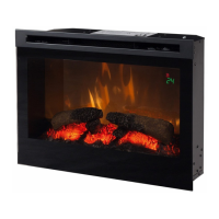
Figure 8
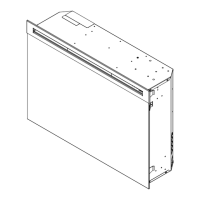
Screws To Remove
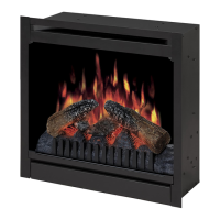
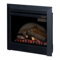
Figure 9
ON/OFF
Switch
Retainer Clips
(one top, one bottom)
from the icker motor and lifting out.
Remove light lter bracket (the metal bracket will have 8.
a tinted lm adhered to it) for easier access to light
bulbs.
Replace light bulbs.9.
Replace light lter bracket and icker rod.10.
Replace the log set by inserting the front edge of the 11.
replace and push down on the rear edge of the ember
bed until it snaps into place.
Lay unit on it’s back and slide front glass back into 12.
position and attach trim.
PARTIALLY REFLECTIVE GLASS
REPLACEMENT
Tools Required: Phillips head Screwdriver
Flat Head Screwdriver
WARNING: If unit was operating prior to servicing allow
at least 10 minutes for light bulbs and heating element
to cool off to avoid accidental burning of skin.
WARNING: Disconnect power before attempting any
maintenance or cleaning to reduce the risk of electric
shock or damage to persons.
Slide replace out of mantel.1.
Lay unit on it’s back for safe removal of front glass.2.
Remove three (3) Phillips screws from the right side of 3.
trim.
Slide glass to right side of replace to remove. (Figure 4.
5)
CAUTION: Even though the glass is safety glass it
may break if bumped, struck of dropped. Care must be
taken when handling the glass.
Pull the front edge of the plastic ember bed or plastic 5.
grate up and forward until the rear tab releases from
the ledge located at the bottom of the partially reective
glass.
!
IMPORTANT: Only handle the log-set by the plastic
ember-bed, not the logs themselves.
!
NOTE: Log-set ts tightly into rebox. Some force
may be necessary to remove.
Loosen but do not remove the two (2) Philips screws on 6.
the retaining clips that hold the partially reective glass
in place, and swivel down so that the retaining clips
clear the edge of the partially reective glass. (Figure 7)
Push the partially reective glass up from underneath 7.
to clear the frame and remove.
Insert replacement partially reective glass top end rst 8.
and lay the bottom end gently in the bottom track of the
frame.
Tighten clips back into place and reassemble replace 9.
in reverse order as described above.
ON/OFF SWITCH REPLACEMENT
Tools Required: Phillips head Screwdriver
Flat Head Screwdriver
WARNING: If unit was operating prior to servicing allow
at least 10 minutes for light bulbs and heating element
to cool off to avoid accidental burning of skin.
WARNING: Disconnect power before attempting any
maintenance or cleaning to reduce the risk of electric
shock or damage to persons.
Remove the rebox from the mantel.1.
Lay unit on its back.2.
Remove the 12 screws that fasten the bottom cover to 3.
the rest of the rebox. There are: two (2) screws on
each side; two (2) screws on the back panel (you may
have to tip the bottom of the replace up if it is laying
on its back), four (4) screws in the front directly under
8 www.dimplex.com