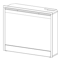
Figure 19
Trim Screws
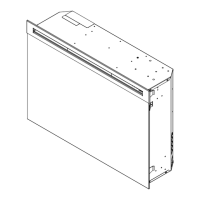
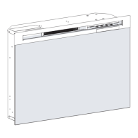
Figure 20
Screws to Remove
13
glass. (Figure 14)
Loosen but do not remove the two (2) Philips screws 6.
that clamp the partially reective glass in place. (Figure
7)
Push the partially reective glass up to clear the frame 7.
and remove - storing it in a safe place away from high
trafc areas.
Coming up from the bottom assembly, in the right, back 8.
corner is a wire with a taped “ANTENNA” label. The
wire is held in place by a loose tting zip tie. Roll the
label around the wire and feed it through the zip tie.
Remove the 12 screws that fasten the bottom cover to 9.
the rest of the rebox. There are: two (2) screws on
each side; two (2) screws on the back panel (you may
have to tip the bottom of the replace up if it is laying
on its back), four (4) screws in the front directly under
the control panel; and two (2) screws on the bottom of
the replace (Figure 8). The bottom panel is now free
to be removed.
Locate the Remote Control Receiver (Figure 18) 10.
mounted underneath the log set support panel and
disconnect the six (6) wiring clips noting their original
locations.
Disconnect the three (3) wire leads from the 3-Position 11.
Switch. (the wires are hard-wired to the Remote Control
Receiver) (Figure 18)
!
NOTE: Using a at head screwdriver gently pry be-
tween the end of the connectors and the switch to release
the wires.
Pull the Antenna wire released in step 8 through the 12.
bottom of the chassis.
Locate the three (3) LED indicator lights from inside the 13.
bottom assembly of the rebox. (Figure 18)
!
NOTE: Using a athead screwdriver, gently push on the
rear edge of the plastic bushing surrounding each LED and
push each LED out from the front of the control panel.
Clear any silicon that may be present and rmly grasp 14.
the sheathed ends of the wires leading to each LED
and remove the plastic pushing from each LED. Each
LED and paired wires can be fed back through the front
control panel and into the bottom assembly area.
The Remote Control Receiver is fastened to the 15.
underside of the ember bed support by four (4)
mounting studs, one in each corner. (Figure 18) Either
squeeze each stud’s clasp to release, or use side
cutters to cut and remove each of the four corner
mounting studs on the board. Clear both ends of
the cut mounting stud from the control board and the
support panel - new mounting studs are supplied with
the replacement part.
Properly orient the replacement Remote Control 16.
receiver and adhere to the control panel with the
supplied/existing mounting studs.
Once the remote control receiver is mounted, 17.
reconnect the LEDs in reverse order as described
in steps 14 - 15 and continue to reconnect and
reassemble the replace in reverse order as described
above.
HEATER ASSEMBLY REPLACEMENT
Tools Required: Phillips head Screwdriver
Flat Head Screwdriver
WARNING: If unit was operating prior to servicing allow
at least 10 minutes for light bulbs and heating element
to cool off to avoid accidental burning of skin.
WARNING: Disconnect power before attempting any
maintenance or cleaning to reduce the risk of electric
shock or damage to persons.
Figure 22
Figure 21
Top Panel
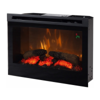
Heater Assembly
Terminal Block
Wires Leading to Bottom Assembly
Heating Element