4
NEW WALL CONSTRUCTION
1. Select a suitable location that is not susceptible to moisture and is away from drapes, furniture
and high traffi c.
2. Place the fi replace in the desired location to see how it will look in the room.
3. Mark the desired location on the fl oor and store the fi replace in a safe, dry and dust free location.
4. Use studs to frame an opening of 30 ¾” wide X 22 5/8” high X 9 3/8” deep.
Option #1 - The power cord can be lead from behind the trim and along the wall to an outlet near the
fi replace.
Option #2 - A new outlet can be installed inside the new frame construction.
Plug the unit into a 15Amp/120Volt outlet. If the cord does not reach, you may use an extension cord
rated for a minimum of 1875 watts.
Option #3 - Hardwire
1. Wire a dedicated, properly fused circuit with 120V,
15amp rating. Allow up to 8 feet of service
cable for connecting power supply to junction box on fi replace when installing after fi nishing wall.
CAUTION
Use two conductor, non-metallic sheath cable with ground wire (3 wires total) for the incoming power
supply on fi replace inserts. Use appropriate wire to meet local and national electrical codes for rated
power consumption.
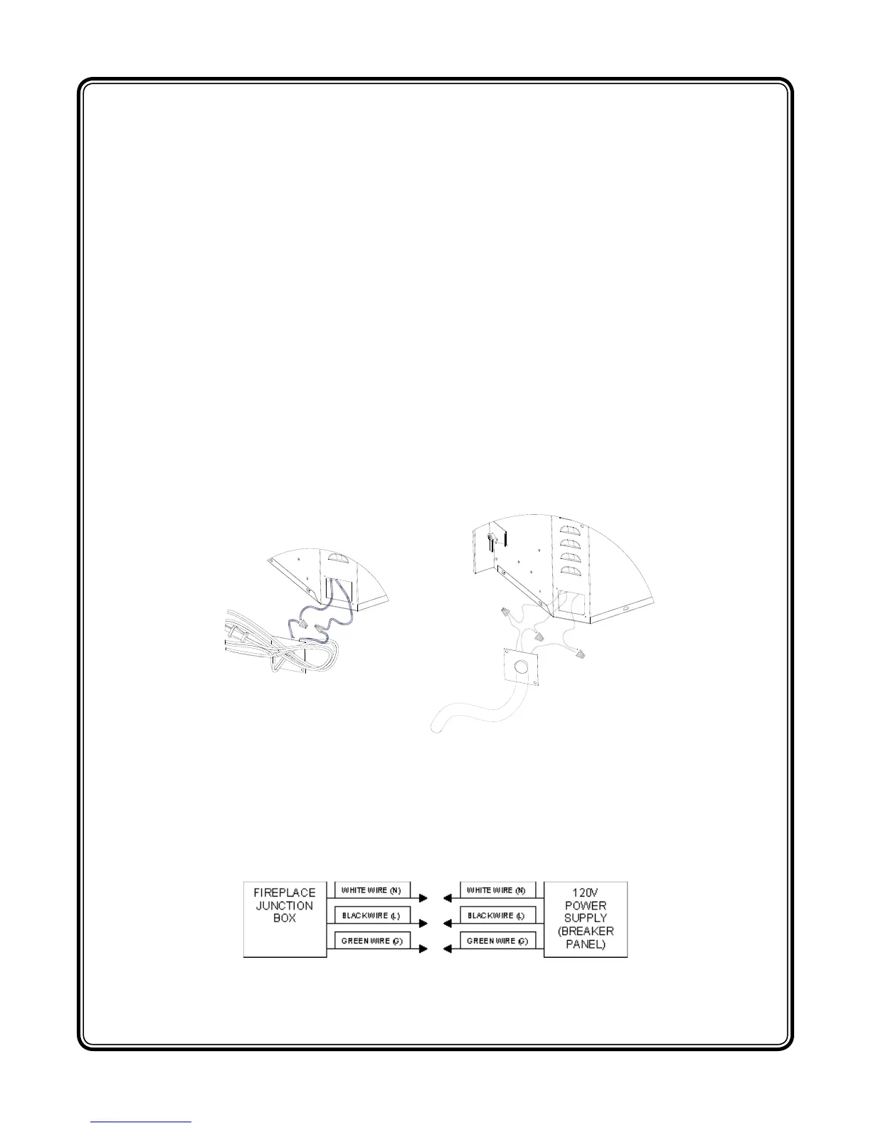
2. Remove the outer jacket and strip the individual conductor from the end.
3. Loosen the screw securing the junction box cover and remove the cover.
4. Take the cables out from the junction box, loosen the two wire twist nuts and remove the cord set.
(FIGURE 3)
5. Route the power supply wire through the knockout on supplied alternative junction box cover and
secure with a wire clamp (not supplied) (FIGURE 4)
6. Connect the black wire (live) from the unit to the black wire from power supply. (FIGURE 4)
7. Connect the white wire (neutral) from the unit to the white wire from power supply. (FIGURE 4)
8. Connect the green wire (ground) from the unit to the green wire from power supply. (FIGURE 4)
9. Place all connectors inside the unit and secure the junction box cover to unit. Ensure that the
cable clamp grips only the jacket of service cable.
FIGURE 4
FIGURE 3