9
then push the switch outward. Alternatively, a at head
screw driver can be used to press the each mounting tab
down individually and pushing the switch out, alternating
sides until the switch is released from its position.
Replace the original switch with the new switch, ensur-8.
ing the correct orientation.
Reconnect the wires according to their original congu-9.
ration.
Re-assemble the remainder of the log grate in reverse 10.
order from the instructions above.
FLICKER MOTOR REPLACEMENT
Tools Required: Philips head screwdriver
Flat head screwdriver
Needle-nose pliers
WARNING: If the log grate was operating prior to ser-
vicing, allow at least 10 minutes for light bulbs and heating
elements to cool off to avoid accidental burning of skin.
WARNING: Disconnect power before attempting any
maintenance to reduce the risk of electric shock or damage
to persons.
Disconnect and remove all of the logs from the unit and 1.
put them in a safe place.
Remove the two (2) screws that secure the icker mo-2.
tor onto the bracket. (Figure 3)
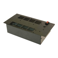
There are four (4) screws that secure the bottom as-3.
sembly to the grate. Remove the four (4) screws and
the whole box can be removed and enable you to have
easier access to everything. (Figure 4)
Remove the ve (5) screws around the Remote Control 4.
Housing. (Figure 6)
Remove the housing being careful not to add any strain 5.
to the wires connecting to the switches.
Trace the wiring from the icker motor to the Remote 6.
Control Receiver and remove the original icker motor
connection and replace with the new wire.
Reassemble the bottom assembly and mount back 7.
on the grate, ensuring that the Flicker Motor wire runs
through the cutout in the outside panel.
Fit the rubber barrier onto the new icker motor and 8.
mount the icker motor onto the mounting bracket. Re-
connect the rubber gasket and icker rod to the icker
motor.
Re-assemble the remainder of the log grate in reverse 9.
order from the instructions above.
 Loading...