Refit the heater to the wall fixing bracket (i.e. follow steps as
in Fig. 4 a, b, c and d) and rotate the bottom fixing bracket
down again and use the screw provided to permanently fix
the heater in place.
The heater should not be connected until the instruction leaflet
is read fully.
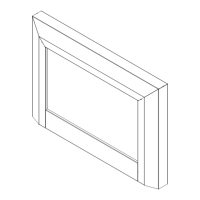
Recessed Installation
Please note that this appliance can also be wall-mounted
so that it is recessed. This can be installed in a large fireplace
opening or a purpose built wall. See Table 1 for size of recess
required and hole fixing dimensions and Fig. 5a. This fireplace
insert does NOT require venting.
In order to ensure it’s future safety in use, it is essential
that this fire is securely fixed to the wall.
IT IS IMPORTANT THAT THE FIXING DEVICE CHOSEN IS
APPROPRIATE TO THE WALL MATERIAL TO WHICH THE
FIRE IS BEING FIXED. SOME MODERN INTERNAL
BUILDING MATERIALS ARE VERY LOW DENSITY BLOCK
AND REQUIRE SPECIALIZED FIXING DEVICES TO
PROVIDE A SAFE,SECURE INSTALLATION.
The installation of this fire should be carried out by a
competent person. If in doubt please consult your local
builder.
This section provides step by step instructions for selecting
a location and preparing the site to install the fireplace into
the following:
Existing Fireplace
1. Make sure that the fire is located on a flat surface.
2. Seal all draughts and vents to prevent chimney debris
from falling onto the Fireplace Insert. Do not install into
an existing fireplace that is prone to dampness.
3. Remove the fire front panel by following the steps as
outlined in ‘Lamp Replacement’ sections.
4. Locate the 4 fixing holes, position the fire accordingly, and
firmly fix the appliance to the wall using the appropriate
screws - see Fig. 5a.
5. Replace the front panel.
New Support Structure Construction
When planning where to position your purpose built support
structure the following steps must be observed:
1. Place the fire in the desired location to see how it will look
in the room.
2. Mark the desired location for the new support structure in
the room and store the fire in a safe, dry and dust free
location.
3. Using timber studs to support the fire, devise and construct
a suitable means of supporting the product within the
wall partition and provide electrical power for the fire to be
HARD wired. For recommended sizes of height, width
and depth of opening for recess and hole fixing
dimensions for each model - see Table 1 and Fig. 5a.
4. When the structure is complete, remove the front panel of
the fire by following the steps as outlined in ‘Lamp
Replacement’ sections.
5. Locate the 4 fixing holes, position the fire accordingly, and
firmly fix using the appropriate screws.
6. Replace the front panel.
TABLE 1
A X Y Z
1160 1143 520 146
NOTE: The appliance should be HARD wired to an electrical
power outlet when placed in a recessed installation.
Please consult a qualified electrician for appropriate wiring
requirements.
Manual Operation
The switches are located at the bottom right side of the
appliance - see Fig. 6.
Remote Operation
The standby switch (S1) must first be turned ‘ON’.
Note: It takes some time for the receiver to respond to the
transmitter. DO NOT PRESS the buttons more than once
within two seconds for correct operation.
Manual & Remote Operation
Setting Operation Setting
Flame Effect Top Neon
Flame Effect & 1kw Heat Press the ‘I’ button Middle Neon
Flame Effect & 2kw Heat Press the ‘I’ button again Bottom Neon
The Standby switch must first be turned ‘ON’ to operate the
appliance manually or by remote control.
Note: It takes some time for the receiver to respond to the
transmitter. DO NOT PRESS the buttons more than once
within two seconds for correct operation.
To go to the previous settings press the O button.
Pressing the O button on the remote turns off the appliance.
To turn the appliance back On press the I button - see Fig. 8.
To increase or decrease the brightness of the flames, use
the dimmer button or the
button on the Remote Control.
To turn off the power the Standby Switch must be turned ‘OFF’.