10 www.dimplex.com
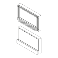
mounting bracket (Figure 2) and carefully place it on a
at surface with the partially reective glass side down.
CAUTION: A protective barrier (i.e. blanket) between
the replace and work surface will help prevent scratches
on the work surface or the replace.
On the back of the replace, remove the eight (16) 5.
screws from the battery access cover and the battery
mounting brackets located in the bottom, right corner of
the back panel (Figure 3).
Lift and remove the battery access cover.6.
Lift and remove the battery out of the housing. 7.
!
NOTE: The battery is heavy so you will need to use
the brackets for leverage to lift it out of the opening. A
at head screwdriver may be helpful for additional lever-
age behind the battery bracket when lifting the battery and
brackets out of the replace.
CAUTION: Take care not to damage the 2 wire connec-
tions on the left side of the battery Figure 8).
Once battery is out of the opening, remove the two (2) 8.
wire lead connectors from the battery spade connec-
tors taking note of their original conguration (Figure 4).
!
NOTE: These wire lead connectors can be pulled off
by using needle nosed pliers to carefully pull the connec-
tors, or a at head screw driver to pry the connectors off the
spades on the battery.
Set the Battery aside.9.
Remove the remainder of the (17) screws which secure 10.
the back panel on to the replace. (3) along the top; (3)
along the right (battery side); (5) along the left (switch
side); and (6) on the bottom lip of the back panel.
Lift the back panel off the unit, exposing the internal 11.
components and set it aside.
Looking at the unit from behind, locate the circuit board 12.
(control panel), on the left hand side of the bottom
panel.
Unplug the wire harness plug connectors on the circuit 13.
board (icker motor; LED light harness, battery wire
harness).
Guide the battery charger input jack out from the left 14.
side of the bottom panel by sliding it up towards you.
Disconnect the wire lead connectors coming from the 15.
circuit board to the switch noting the original congura-
tion.
!
NOTE: Pliers can be used for a better grip on the con-
nector, or a at head screw driver can be used to carefully
pry up between the switch and connector if you are unable
to pull it off.
!
NOTE: Try not to reverse the two black wires on the
switch. Their positioning on the circuit board to the switch
is: (Figure 5)
Red-1, Black-2 goes to the side of the switch farthest •
from the circuit board, Black-2 on the spade in the cen-
ter of the switch and Red-1 on the spade on the right
side;
Black-3, Yellow-4 goes to the side of the switch closest •
to the circuit board, Black-3 on the spade in the center
of the switch and Yellow-4 on the spade on the right
side of the switch.
Carefully pull the (3) charge level indicator lights with 16.
wires out from their mounting clips near the switch
noting their original order, (Green in the clip to the left
closest to the switch, Yellow in the center; Red in the
clip on the right).
!
NOTE: There is rubberized glue securing these in the
clip. When pulling on the indicator lights, the glue will come
off with the bulb & wires.
!
NOTE: If necessary, using pliers may allow for a bet-
ter grip when pulling these bulbs out.
Remove the circuit board from the mounting clips 17.
located on the 4 corners of the board. Use a pair of pli-
ers to pinch the tip of each mounting clip or cut the tabs
off so the original board can be pulled off.
Push the remainder of the old tabs out through the bot-18.
tom panel and replace with the new tabs provided with
the replacement circuit board.
Line up the 4 corners of the replacement board to the 19.
(4) mounting tabs and carefully push the new board
down onto the tabs.
Connect all of the wires and harnesses according to 20.
their original conguration.
!
NOTE: Ensure that the switch wires and the battery
level indicator lights are in their correct order and locations
as described in step 15 and 16.
Re-assemble the remainder of the replace in reverse 21.
order.
!
NOTE: Before placing the battery back in the housing/
brackets, ensure that the battery wire leads are re-connect-
ed in their original position with black leading to black and
red leading to red to ensure correct polarity and that they
are not pinched when replacing the access cover.