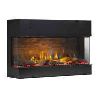
Fireplace Installation
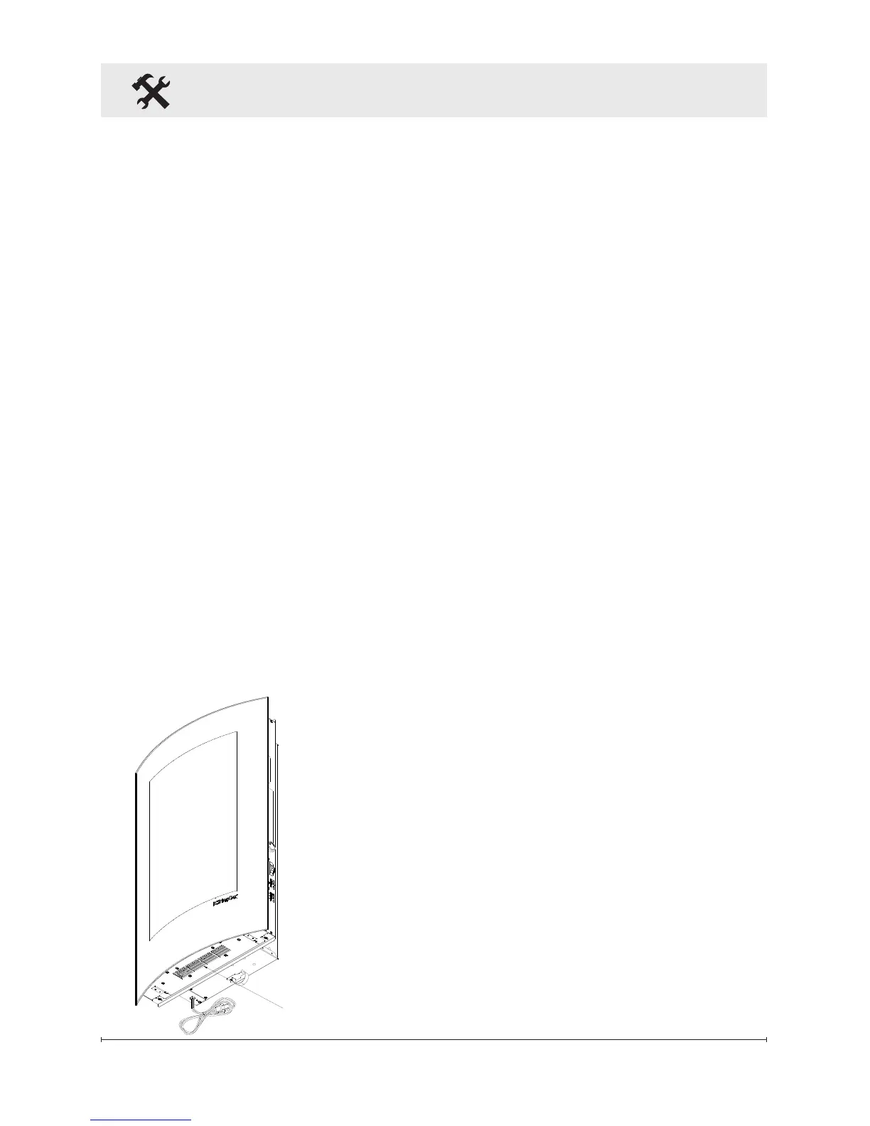
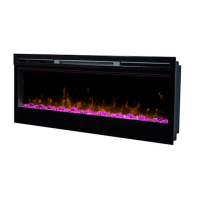
for heat exhaust from the bottom
of the replace (Figure 3).
With a wall stud nder, locate 3.
the center of the wall stud,
drive a wood screw into the
stud and leave approximately
⅛" (3 mm) exposed threads
for the replace to hang on.
The second mounting point 4.
should be picked such that it
is farthest (to the left or right)
relative to the rst one among
the seven (7) keyholes (A to
G shown in Figure 2) on the
replace for wall mounting,
these keyholes are 2" (51
mm) apart. For example, if
you plan to use hole B as
the rst mounting hole, the
second mounting hole must
Figure 3
Heat Exhaust
be G.
Other available combinations
are A-G, C-G, A-F, A-E, A-D
and D-G.
Mark the second mounting 5.
screw location; ensure that it
is level with the rst with the
help of the provided bubble
level and the replace itself.
Screw the threaded drywall
anchor in the drywall with a
Philip’s head screwdriver until
the head is at against the
wall surface.
Caution should be taken
when using a power tool to
install a threaded drywall
anchor as the drywall may
distort, tear or slightly buckle
as a result of over-torque.
With a Philip’s head screw 6.
driver, screw the drywall
anchor screw into the drywall
anchor already in the wall,
leave ⅛" (3 mm) exposed
threads for mounting the
replace.
With the glass assembly 7.
taken off, mount the rebox
onto the two (2) mounting
screws.
Mark position of hole “H”.8.
Remove replace from wall.9.