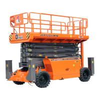
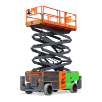
OPERATOR’S MANUAL with Maintenance Information
Maintenance
48
10 Check the battery acid level. If needed,
replenish with distilled water to 1/8 inch I 3
mm below the bottom of the battery fill
tube. Do not overfill.
11 Install the vent caps and neutralize any
electrolyte that may have spilled.
All models:
12 Check each battery pack and verify that
the batteries are wired correctly.
13 Inspect the battery charger plug and pigtail
for damage or excessive insulation wear.
Replace as required.
14 Connect the battery charger to a properly
grounded 110 - 230V / 50 – 60 Hz single
phase AC power supply.
⊙ Result: The charger should operate and
begin charging the batteries.
¤ Result: If, simultaneously, the charger alarm
sounds and the LEDs blink, correct the
charger connections at the fuse and battery.
The charger will then operate correctly and
begin charging the batteries.
Note: For best results, use an extension of
adequate size with a length no longer than
15m.
Note: If you have any further questions
regarding the battery charger operation,
please contact the DINGLI Service
Department.
B-2
Inspect the Electrical Wiring
DINGLI requires that this procedure be
performed every 250 hours or quarterly,
whichever comes first.
Maintaining electrical wiring in good condition
is essential to safe operation and good
machine performance. Failure to find and
replace burnt, chafed, corroded or pinched
wires could result in unsafe operating
conditions and may cause component
damage.
Electrocution / burn hazard.
Contact with electrically charged circuits could
result in death or serious injury. Remove all
rings, watches and other jewelry.
1 Inspect the underside of the chassis for
damaged or missing ground strap(s).
2 Inspect the following areas for burnt,
chafed, corroded and loose wires:
· Ground control panel
· Hydraulic power unit module tray
· Battery pack module tray
· Platform controls
· Engine
3 Inspect for a liberal coating of dielectric
grease in the following locations:
· Between the ECM and platform controls
· Engine ECM
· All wire harness connectors
· Level sensor
4 Turn the key switch to ground control and
turn the ground red Emergency Stop
button clockwise to the on position pull out
the platform red Emergency Stop button to