2. CONNECTION TO THE LOAD RECEIVER
2.1 ANOLOG LOAD CELLS
IMPORTANT: Respect the electrical precautionary measures indicated in section 1.
After having followed the instructions regarding the platform or the load receiver, the screened cable leading from the load
cell(s) must be connected to the instrument through the CELL1 terminal board and the CELL1, CELL2, CELL3, CELL4
connectors; see section 8.
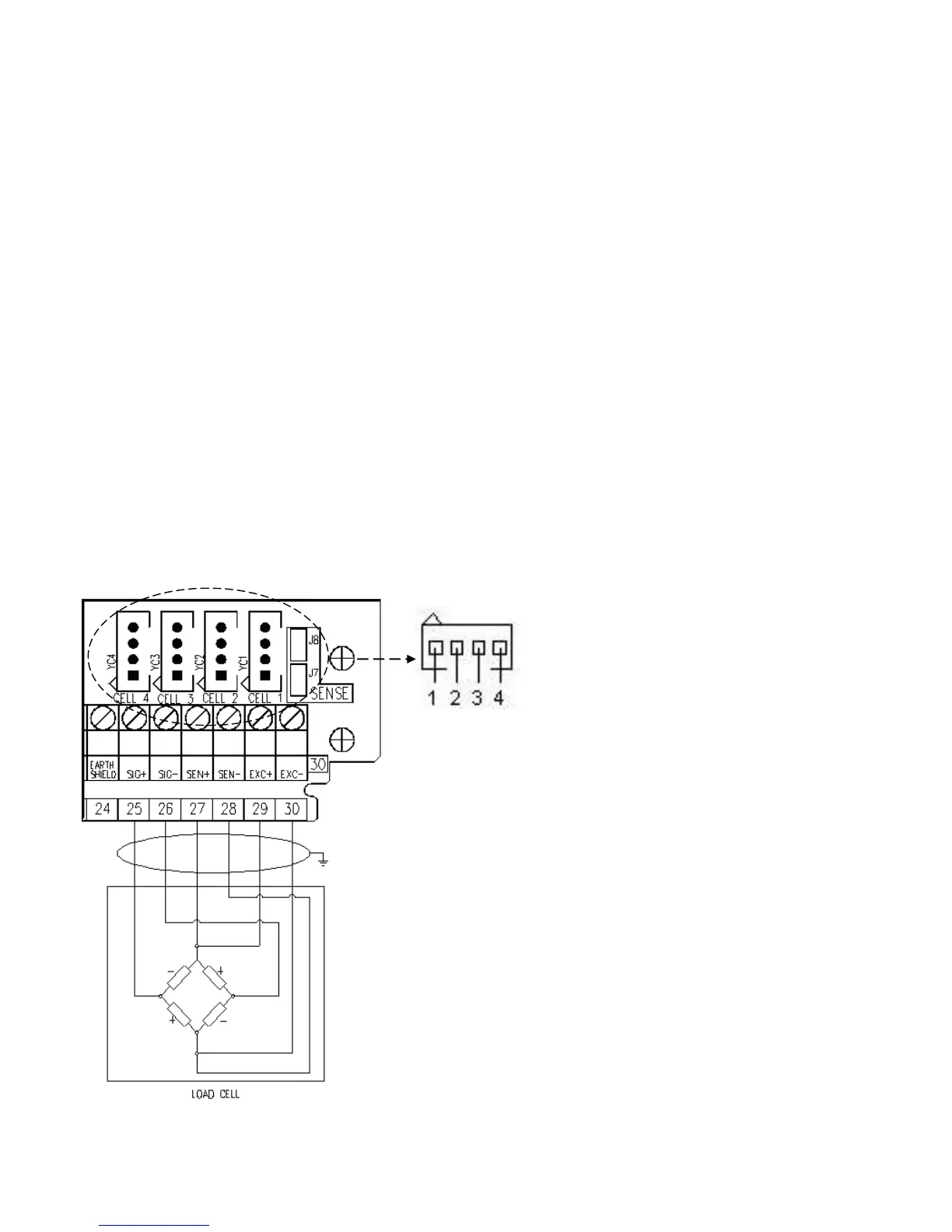
The terminal board of the indicator may be connected to the 6-wire load receiver (with use of SENSE), or simply 4-wire; for
this, through jumper J7 and J8 it is possible to choose whether to short-circuit the SENSE with the POWER SUPPLY
(jumpers closed) or not (jumpers open).
The SENSE allows compensating for any drops in voltage in the part of the cable that connects the instrument to the
transducer. It is useful when the distance between the indicator and the transducer is greater than 10 m.
The 4-pin connectors instead allow just the 4-wire connection.
To make the connection qualified personnel must open the instrument (see terminal board connections section 8).
TAKE NOTE: if there is just one LOAD RECEIVER, it is possible to make a 6-wire connection (use of sense) directly
with the terminal board, removing the J7 and J8 jumpers.
If there are two or more LOAD RECEIVERS, one should close the J7 and J8 jumpers (sense and power supply are
short-circuited) and make the 4-wire connection.
Normally the indicator comes already connected to the platform and is ready to use. If this is a LEGAL FOR TRADE
instrument, access to the connection will be subject to a legal SEAL.
Follow the instructions for preparing the platform for use.
AMP 4 CONNECTOR
1. EXC + POWER SUPPLY +
2. EXC - POWER SUPPLY -
3. SIG + SIGNAL +
4. SIG - SIGNAL -
TERMINAL
25. SIG + SIGNAL +
26. SIG - SIGNAL -
27. SEN + REFERENCE +
28. SEN - REFERENCE -
29. EXC + POWER SUPPLY +
30. EXC - POWER SUPPLY -
See section 8 for further information.

 Loading...