7
403.GM10 4.16 2011 Chevrolet Cruze
© 2019-03-01 Directed. All rights reserved.
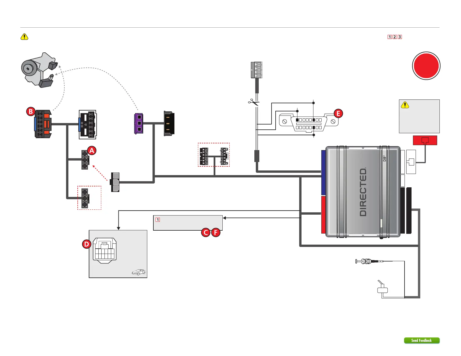
Refer to "Pre-installation and application warnings" for important information, such as the description of each special note referenced in the diagram ( ).
D2D
only
Wiring diagram with T-Harness (THGM610D Rev.1&2)
Use connectors
labeled GM10
3-pin
connectors
GM 10
GM 10
GM 06
NOT USED
Hood Pin
Note: The hood pin is only required on vehicles
that are not equipped with a factory hood pin.
You can connect
to either a XL202
RFTD OR a SmartStart
module. Refer to the
SmartStart/XL202
Installation Notes for
more information.
Remote Start Safety
Override Switch
Ignition Connector
(black connector at
ignition switch)
To
Immobilizer
Control Module
(violet connector
under ignition
switch)
Away from
Immobilizer
Control Module
(vehicle side)
Ignition Barrel
NOT USED
HS CAN Low: Pin 14
HS CAN High: Pin 6
SW CAN: Pin 1
16
8
9
1
OBDII Diagnostic
(connector side view)
Cut
4-pin
White
Connector
Cut away the 4-pin
connector and connect
the three wires to the
OBDll 16-pin connector.
HS CAN High: Tan/Black
HS CAN Low: Tan
SW CAN: Lt. Green
3-pin
connectors
T-01
T-02
(-) Parking Lights Output: Black/White
(-) RAP Off Output: Green/Black
1 2 3 4 5
7
6
121198 10
Headlight Switch
(black 12-pin connector)
(-) Parking Lights: Pin 3, 5 or 7
Refer to the
Vehicle
connections
section for the
corresponding
connector, pin
and wire color
of your vehicle.
(-) Driver Door Trigger
Refer to the Vehicle connections section.
To
Vehicle
To
Ignition
THGM610D Rev.1 & 2 (Optional T-Harness)