9
© 2012 Directed. All rights reserved.
3 pin Door Lock Harness
GREEN (-) 200mA LOCK OUTPUT
EMPTY NOT USED
BLUE (-) 200mA UNLOCK OUTPUT
GREEN (-) LOCK OUTPUT
Connect to a wire that pulses ground to activate the vehicle door lock relay. (Usually at the door lock switch
or BCM).
[Optional connection for both configurations]
BLUE (-) UNLOCK OUTPUT
Connect to a wire that pulses ground to activate the vehicle door unlock relay. (Usually at the door unlock
switch or BCM).
[Optional connection for both configurations]
NOTE: For door lock wiring diagrams refer to document #1041 under the Resources tab at www.di-
rectechs.com
5 pin RKE (Remote Keyless Entry) Harness
GRAY/BLACK (+) OEM TRUNK SHUNT INPUT
RED/BLACK (+/-) DISARM DEFEAT INPUT
RED (+) DISARM INPUT
GREEN/BLACK (+/-) ARM DEFEAT INPUT
DARK GREEN (+) ARM INPUT
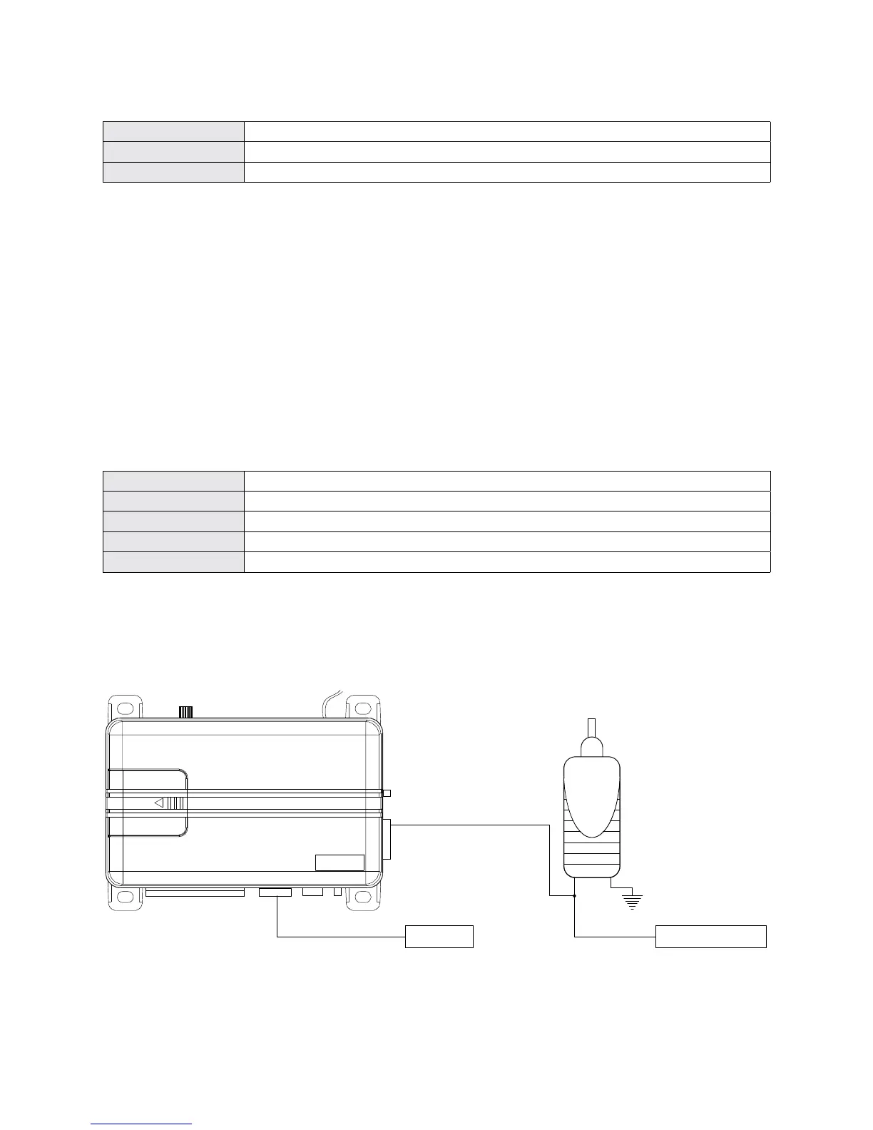
GRAY/BLACK (+) TRUNK SHUNT INPUT
Connect to a wire that pulses (+)12V when the OEM trunk release is activated. If the system is armed when
the trunk is opened with the OEM remote, the shock sensor and trunk trigger will be bypassed until the trunk
is closed. See diagram below for sensor shunt wiring information.
NOTE: The blue (-) trunk pin input must be connected for feature to work correctly.
GRAY/BLACK (+)
Shunt Input
(+) Trunk Release
Motor Wire
BLUE (-)
Trunk Pin Input
ALARM MODULE
To Trunk Pin
To BCM/Control Relay
Trunk Release
Solenoid
[Optional add-on security connection]