© 2004 Directed Electronics, Inc. Vista, CA
2299
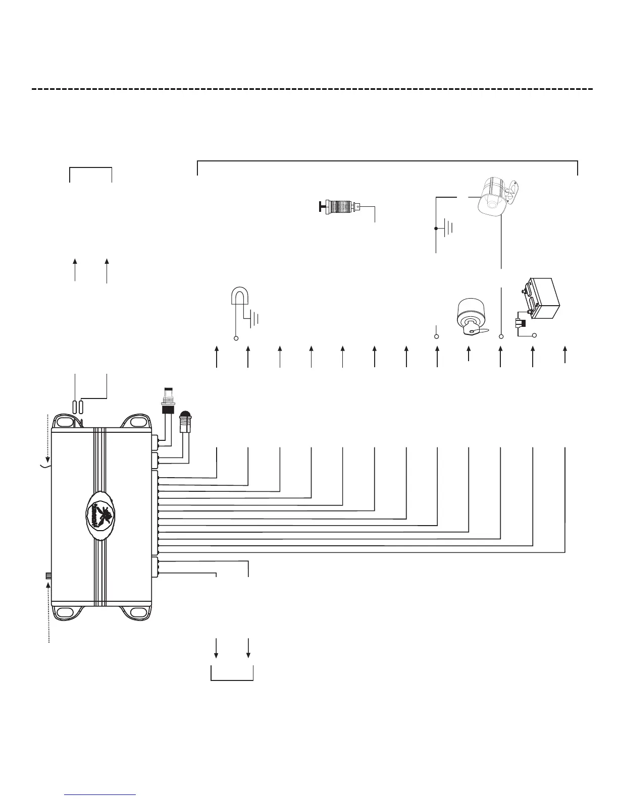
wwiirriinngg qquuiicckk rreeffeerreennccee gguuiiddee
Blue
(+) Lock, (-) Unlock
Output
Green
(-) Lock, (+) Unlock
Output
LED
Valet Switch
To Optional Sensor or Accessory
Factory Trunk Release
Relay (0ptional)
Orange
(Ground When Armed)
(-) 500 mA
White
(Selectable Light Flash)
(+/-) 10A
White/Blue (-)
Channel 3 Auxiliary Output
(-) 200 mA
Black/White
(Interior Illumination)
(-) 200 mA
Yellow
(+) Ignition Input
Zone #5
Green
(Door Trigger Input)
(-) Zone #3
Blue
(Trunk/Hood Input)
(-) Zone #1
Violet
(Door Trigger Input)
(+) Zone #3
Black (-)
(Chassis Ground)
Brown
(Siren output)
(+) 1A
Red (+)
(Constant Power)
Red/White
(-) 200 mA Channel 2
Auxiliary Output
(-) 200 mA
Chassis Ground
Optional Accessories
Interior Light Illumination Relay
(Optional)
Negative Door Pin Switch
Negative Trunk Pin (Optional)
Positive Door Pin Switch
Red
Black
(+/-) Vehicle
Parking Light Wire
Fuse
DIA-349
Impact Sensor
Sensitivity
Black
(Starter Interrupt Input/Output)
Black
(Starter Interrupt Input/Output)
(These wires are interchangeable)
Starter Motor/
Starter Motor Relay
Key Side of Starter
12-Pin H1
Primary Harness
3-Pin, 2-Wire
H2
Door Lock
Harness
Antenna
H1H2
H
3
H3 Starter Interrupt
Plug-in Harness
 Loading...