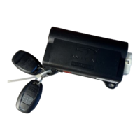
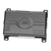
Do you have a question about the Directed Electronics 561T and is the answer not in the manual?
Identifies the source for constant 12V power supply in the vehicle for system connection.
Details how to locate the vehicle's starter wire using a multimeter for proper connection.
Explains how to identify the 12V switched ignition wire using a multimeter.
Guides on locating the vehicle's accessory wire, crucial for climate control systems.
Instructions for locating the positive parking light wire, often near the light switch.
Details on finding the tachometer wire using AC voltage measurement for RPM sensing.
Procedure for finding the wait-to-start bulb wire in diesel vehicles for glow plug timing.
Details the H1/1 wire's function for factory security disarm and its relay connection.
Explains the H1/2 wire's function for factory alarm rearm and its relay connection.
Describes the H1/3 YELLOW wire's use as an ignition output for aftermarket RF systems.
Details the H1/4 input for remote start activation pulses, specifying 2 pulses.
Explains connecting H1/5 to the diesel wait-to-start bulb, noting polarity and diode use.
Describes the H1/6 input for remote start activation, requiring 2 consecutive 12V pulses.
Provides instructions for making a secure chassis ground connection with the H1/8 wire.
Explains the H1/9 wire for light flash output, covering polarity and jumper settings.
Details connecting the RED wires to a high current 12V source for relay satellite power.
Specifies connecting the PINK wire to the vehicle's ignition wire.
Guides connecting the ORANGE wire to the vehicle's accessory wire, often for climate control.
Instructs connecting the PURPLE wire to the vehicle's starter wire.
Explains connecting PINK/WHITE for a second ignition or accessory circuit.
Details connecting H2/1 to the neutral safety switch for safe remote start operation.
Explains connecting H2/2 for tachometer signal input to monitor engine RPMs.
Instructs connecting H2/3 to the brake light wire for shutdown when the brake pedal is pressed.
Details connecting H2/4 to the hood pinswitch to disable remote start when the hood is open.
Explains the H2/5 output for status indication or defogger activation.
Details Passlock I and II systems in GM vehicles and required bypass modules.
Covers Passkey III and other transponder systems, listing compatible vehicles.
Explains the TACH THRESHOLD jumper for adjusting tach signal sensitivity in certain vehicles.
Details the LIGHT FLASH jumper for setting parking light output polarity.
Describes the engine checking feature for monitoring vehicle status during remote start.
Explains tachometer or voltage sensing for engine verification during remote start.
Details the programmable run time for the remote start system, default 12 minutes.
Describes setting for parking lights to flash or remain constant during remote start.
Sets the engine cranking duration for vehicles using voltage sense.
Adjusts voltage threshold for engine running verification in voltage sense mode.
Allows programming the number of pulses to activate or deactivate the remote start.
Details using the PINK/WHITE wire for a second ignition or accessory output.
| Remote Start | Yes |
|---|---|
| Keyless Entry | Yes |
| Panic Mode | Yes |
| Shock Sensor | Yes |
| LED Status Indicator | Yes |
| Compatibility | Universal |
| Starter Kill | Yes |
| Door Lock Control | Yes |
| Trunk Release | Yes |
| Valet Mode | Yes |
| Battery Backup | No |
| Function | Security |
| Remote Control | Yes |
| Type | Car Alarm System |

