Do you have a question about the Directed Electronics 100 ESP and is the answer not in the manual?
Wire supplies 500 mA ground when armed. Controls DEI starter kill relay.
Wire provides 200 mA output to flash parking lights.
Wire provides 200 mA output for Channel 3 activation.
Wire outputs 200 mA to drive a domelight supervision relay.
Wire outputs 200 mA for progressive unlock of passenger doors.
Describes Type A door lock wiring using positive 12V pulses.
Describes Type B door lock wiring using negative pulses.
Details interfacing with reversing polarity door lock systems.
Explains controlling aftermarket actuators for door locks.
Describes door lock interface for Mercedes-Benz and Audi vehicles.
Details interfacing with Type F one-wire door lock systems.
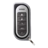
Assigns transmitter button functions for arm/disarm, channel 2, and channel 3.
Configures transmitter for factory keyless entry style operation.
System arms automatically after ignition off (passive) or only via transmitter (active).
Controls horn honks for system arming and disarming confirmation.
Automatically locks doors three seconds after ignition is turned on.
Automatically unlocks doors when the ignition is turned off.
Determines if doors lock during passive arming or only when armed via transmitter.
Turns on the domelight for 30 seconds after ignition is turned off.
Sets door lock pulse duration, e.g., 3.5 seconds for European vehicles.
Enables two pulses for unlocking doors, accommodating specific vehicle systems.
Activates starter kill and triggered sequence with ignition when ON.
Enables Code Hopping technology for enhanced security.
| Remote Control | Yes |
|---|---|
| Shock Sensor | Yes |
| Starter Kill | Yes |
| Door Lock Control | Yes |
| Trunk Release | Yes |
| Panic Alarm | Yes |
| Valet Mode | Yes |
| LED Indicator | Yes |
| System Type | Security |
| Alarm Type | Car |
| Range | 1500 feet |