© 1999 Directed Electronics, Inc. Vista, CA 11
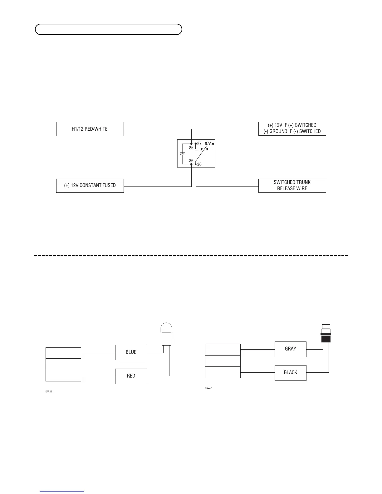
When the system receives the transmitter code controlling Channel 2 for longer than 1.5 seconds, the red/white
wire will supply an output as long as the transmission continues. This is often used to operate a trunk/hatch
release or other relay-driven functions.
IMPORTANT! Never use this wire to drive anything but a relay or a low-current input! The transis-
torized output can only supply 200 mA of current. Connecting directly to a solenoid, motor, or other
high-current device will cause it to fail.
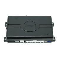
plug-in LED and valet/program switch
The LED and the Valet/Program switch both plug into the control module. The status LED plugs into the small
two-pin port, while the Valet
®
/Program switch should be plugged into the larger blue two-pin port. The status
LED and Valet
®
/Program switch each fit into
9
/32-inch holes.
Status LED Valet
®
/Program Switch
H1/12 RED/WHITE channel 2, 200mA (-) output