� |POWER LAN
�Coax Statu s
�Coax NTWK
�WLAN
�AP|STA
� |POWER L AN
�Coax Sta tus
�Coax NTW K
�WLAN
�AP|STA
Figure 3
TabletopInstallation
TheDIRECTVCINEMA™ConnectionKit(DCCK)unitshouldbeplacedonthebaseplate(Figure1)byinsertingthebaseplate
knobsintoknobholesA&B(Figure2).Shiftthebaseplatetothelefttotightenontotheunit asshowninFigure3.
WallMountInstallation
Wallmountinstallationoptions:
1. Wallmounttheunitwiththebaseplate.
2. Wallmounttheunitdirectlyonthescrews.
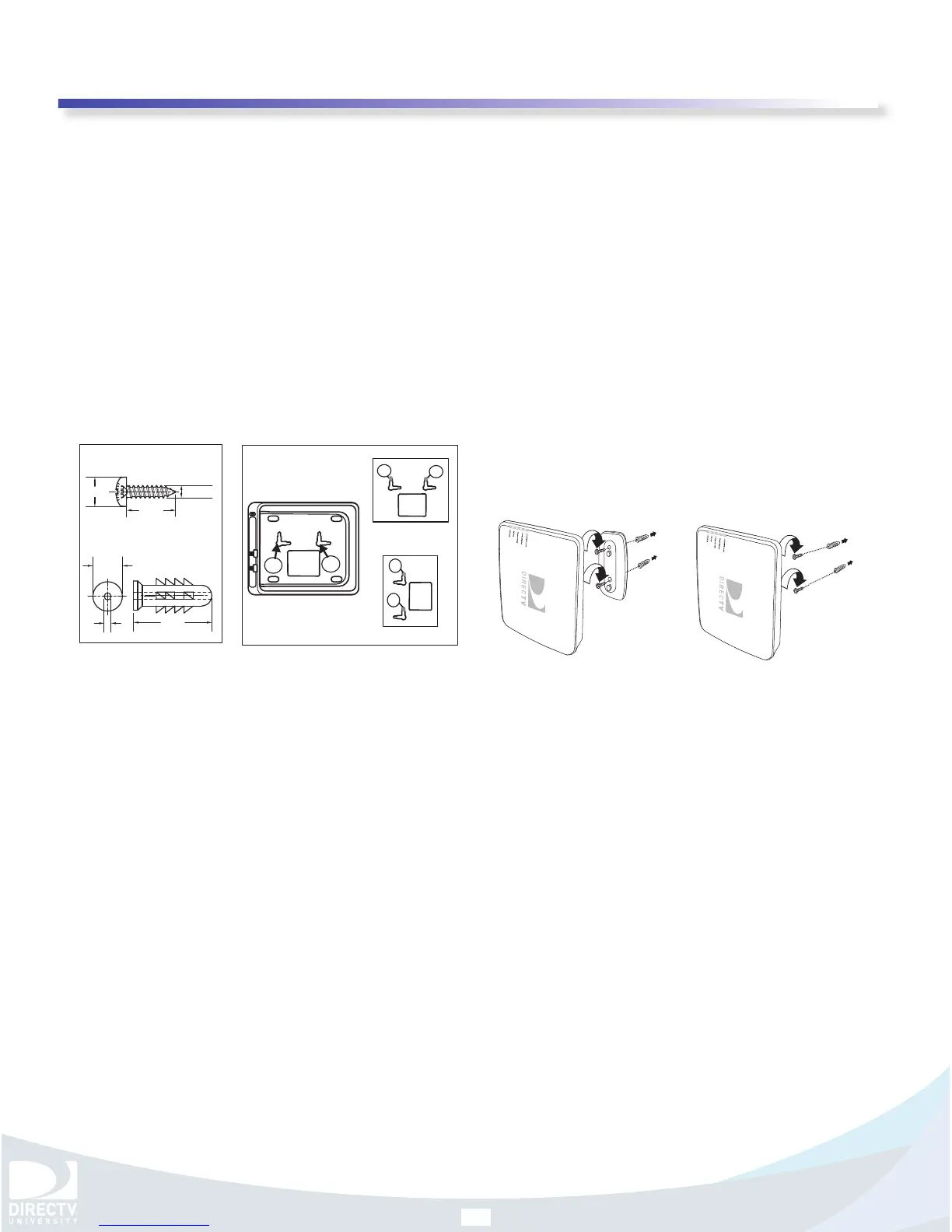
TwoM4x20mmpanheadscrews(threadtype:tapping)andexpansionanchors(Figure4)areincludedforwallmounting.
YoucancallDIRECTVfordetailedinformation.
*HorizontalorientationusingpointsC&D(Figure5‐1)orverticalorientationusingpointsC&D(Figure5‐2).
*Suitablemasonryscrewexpansionanchorsmayberequiredifattachingto stone/brickwall.
y Tomounttheunitonawall,followtheseinstructions:
1. Ensurethatthemountinglocationisfreefromha zards(electricitycables/pipesetc).
2. Decideorientation:horizontalorvertical.
3. Drilltwopilotholes26mm(about1.0inches)deepusinga3.6mm(about0.14inches)drillbit.
à Forhorizontalorientation,thetwopilotholesmustbelevelandspaced70mm
(about2.76inches)apart
horizontally.
à Forverticalorientation,thetwopilotholesmustbeverticalandspa ced70mm(about2.76inches)apartvertically.
à Whenmountingonastudpartitionwallat leastoneofthemountingscrewsmustbeattachedtoawoodenstud.
4. Decidewallmountmethod:
à Withbaseplate:PlacethescrewexpansionanchorsintothedrilledholesÆdrivethescrewsthroughthebaseplate
andfastentothewallÆmounttheunittothebaseplateproperly.SeeFigure6.
à Withoutbaseplate:PlacethescrewexpansionanchorsintothedrilledholesÆdrivethescrewsintothewallÆ
adjustthescrewstoexposeapproximately5.5inchesofthescrewtomounttheunitproperly.SeeFigure7.
5. MakesurethatthecorrectslotsofknobholesCandD(Figure5)areuseddependingonorientation.
mm
3.75 ~ 4.25mm
20
7mm
25mm
2.9mm
8mm
Screw
Expansion Anchor
Figure 4
Figure 5
C
D
Figure 5-1
C
D
Figure 5-2
C
D
Figure 6
1
3
2
Figure 7
1
3
2