18
Appendix C:
Description of Views
Pictures and Diagram of the MARCUS® 3G Radio
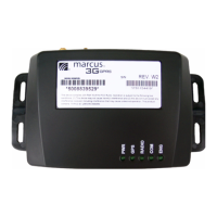
Top View with LEDs
MARCUS® 3G Radio Module
MARCUS® 3G Radio Module Top View
USB: USB Connector Port
SIM DOOR: SIM Tray
PWR: Device is powered
- GREEN Permanently ON - Device Functional
- Permanently OFF - No Power or Device Nonfunctional
GPS: GPS fix is valid
RADIO: GPRS modem transmitting
COM: Device online with MARCUS® Servers
ENG: Ignition is powered
- GREEN Permanently ON - Engine ON
- Permanently OFF - Engine OFF
Back View Connector Layout
MARCUS® 3G Radio Module Back View
MARCUS® 3G Radio Module Back View
Left Connector: (8 pin) Power 12 Volts DC 3 wire install with
optional Aux lines 3 Inputs / 2 Outputs
NOTE: Power connection must be wired in the following manner:
RED Wire = Constant 12 Volts, Pin 7
Black Wire = Chassis Ground, Pin 8
White Wire = Switched Ignition, Pin 6
RS-232/DB9 Port: Serial port connector
Center Connector: GPS Connector / SMB Male Snap-on
Right Connector: RF Connector / SMA Female Screw-on
MARCUS® 3G Radio Module Wiring Diagram
MARCUS® 3G GPRS Radio Module
DW-A0003-W2
Combo GPS - Radio Antenna: Glass mount with TX/RX side toward the
glass on lower passenger side windshield.
NOTE: Sensors are connected through Pin 1-5. Power
connectors are through Pins 6-8.
AUX/I Orange wire; Pin 1 can be configured to monitor powered sensors
(+12 Volts trigger).
AUX/I Green wire; can be configured to monitor negative sensors (Ground
trigger).
Recommended that Constant and Switched power be wired through a
fused circuit (in-line fuse, 3 amps).
Important: Failure to properly wire the MARCUS® 3G Module will cause
faulty operation.
 Loading...