3
Contents____________________________________________________
This manual covers the following:
1 INTRODUCTION
1.1 Introduction to the MARCUS
®
3G Radio Module 4
1.2 Overview 4
1.3 MARCUS
®
3G Radio Module (MRM) Hardware 4
1.4 MARCUS
®
3G Wiring Diagrams 6
2 EQUIPMENT AND TOOLS
2.1 Recommended Tools 6
2.2 Recommended Supplies 6
3 ANTENNAS
3.1 General Antenna Guidelines 7
3.2 GPS Antenna 7
3.3 RF Antenna 7
3.4 Combo GPS/RF antenna 8
4 VEHICLE WIRING
4.1 To Connect Power 9
4.2 Using Wire Crimp 9
4.3 Securing Ground Wire 10
4.4 Power Specifications 10
5 RADIO MODULE LOCATION
5.1 Radio Module Location 11
5.2 Radio Module Placement 12
5.3 Radio Module Mounting 12
6 AFTER INSTALLATION TESTING
6.1 In the Field 13
6.2 Over the Internet 13
7 TROUBLESHOOTING AN INSTALLATION
7.1 Troubleshooting Guide 14
8 APPENDIX A: INSTALLATION OF THE MARCUS PTO/DOOR SENSOR 15
9 APPENDIX B: INSTALLATION INFORMATION SHEET 17
10 APPENDIX C: TECHNICAL PICTURES OF MARCUS 18
11 APPENDIX C: TECHNICAL SPECIFICATIONS 19
List of Figures and Pictures
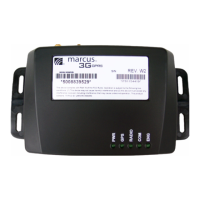
1.2.1 Picture - MARCUS
®
3G Radio Module
1.2.2 Figure - MARCUS
®
3G Radio Module with Combo GPS/RF antenna & pwr harness
3.3.1 Picture - Example Placement of Glass Mount GPS and RF Antennas
3.3.2 Picture – Example Placement of Combo GPS and RF antenna
4.1 Picture - Example Placement of MARCUS
®
Radio Module inside dashboard
4.2 Picture - Example Placement of MARCUS
®
Radio Module inside dashboard
4.3 Picture - Example Placement of MARCUS
®
Radio Module inside dashboard
5.1 Picture - Proper use of in-line power crimp
5.2 Picture - Proper placement of electrical ground wire
5.3 Figure – MARCUS
®
3G Radio Connector Pin Layout

 Loading...