Installation Diagrams - Diagram 14. 110°, 118.7°, 119°, & 129° (DISH 1000+) 3 - 17
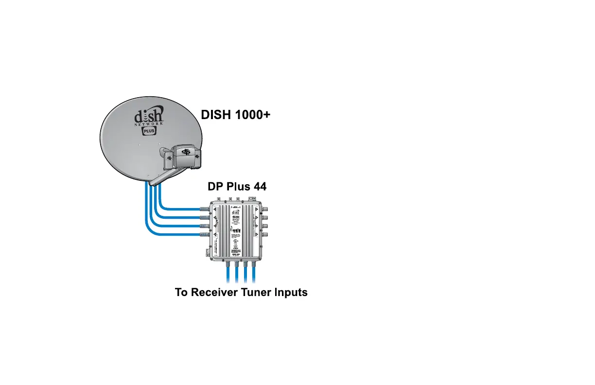
Diagram 14. 110°, 118.7°, 119°, & 129° (DISH 1000+)
Uses DP 500+ LNBF Assembly, DISH 1000+ Bracket, DISH Pro Dual, and DISH Pro Plus 44
• Each DP Plus 44 Switch requires a
Power Inserter on T
O POWER INSERTER
P
ORT 1.
• Single-cable/dual-tuner receiver
installations require a DP Plus
Separator.
• Grounding according to the National
Electric Code (NEC) and all local
electrical codes is required.
• 118.7° should be connected to fourth
input of switch.