9/12
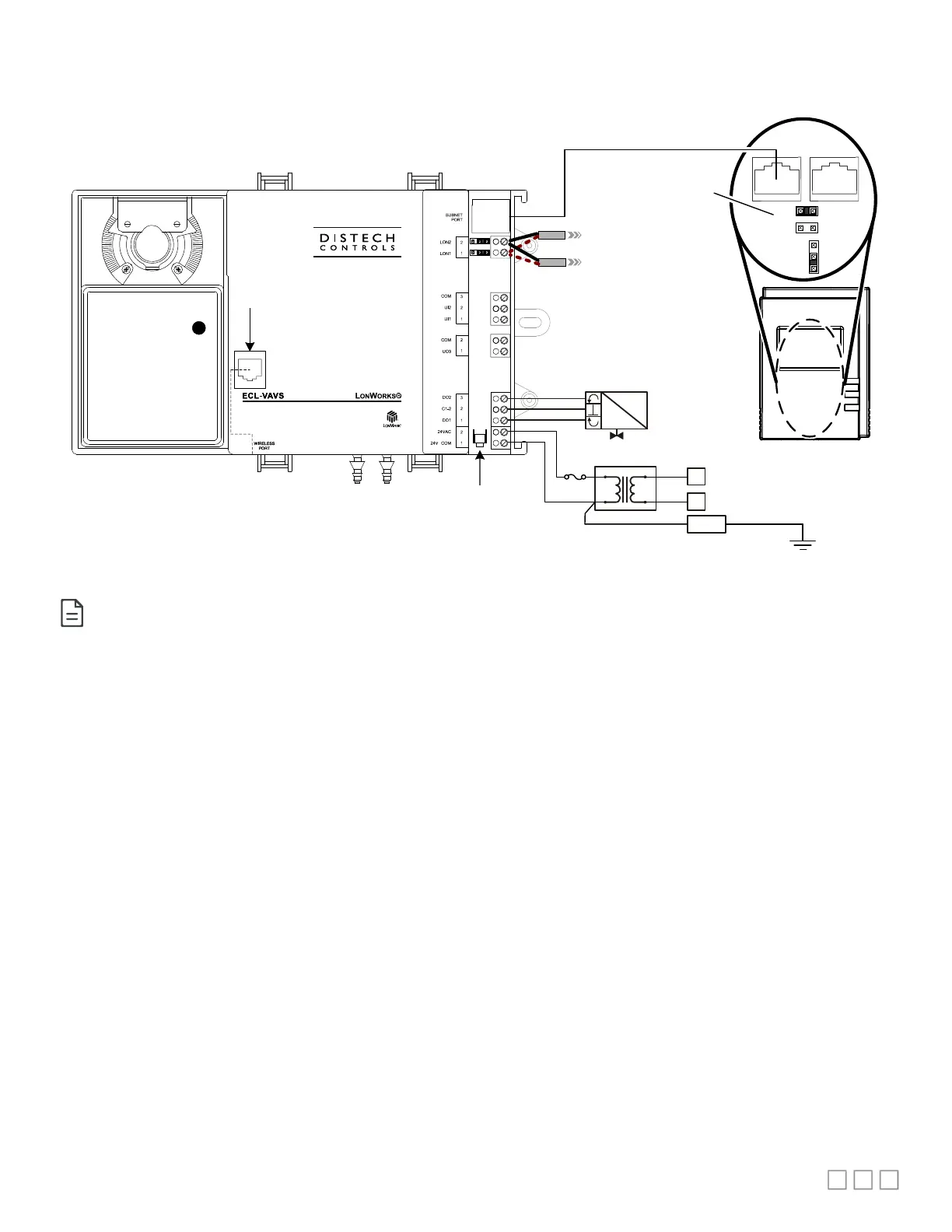
Typical Variable Air Volume Application Wiring Diagram
PRESSURE
LOWHIGH
®
From Previous Device
To Next Device
24
VAC
N
L
120 /
220 VAC
OPTIONAL:
Connect to Electrical System Ground
Fuse
GND
Allure
EC-Smart
-Vue
EOL Enabled at the
last sensor at the end
of the Bus
ON
EOL
OFF
Heating Floating
Actuator
L
ON
W
ORKS
Network
Back of Allure
EC-
Smart-
Vue
Wireless Port
(beneath cover)
E
D
E
D
Service PIN
Button
BAC
LON
Figure 14: Typical Power and Network Connections with an Allure EC-Smart-Vue Input and Floating Actuator Output
Although only the Allure EC-Smart-Vue is shown here, any other Allure Series Communicating Sensor can be connected to the subnet port in
this manner. Refer to the sensor’s corresponding Hardware Installation Guide for more details.

 Loading...