EasyManua.ls Logo

Distech Controls ECLYPSE ECY-VAV User Manual

Distech Controls ECLYPSE ECY-VAV
16 pages
To Next Page IconTo Next Page
Page #1 background imageLoading...
Page #1 background image
ECLYPSE Connected VAV Controller
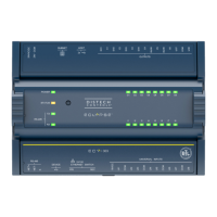
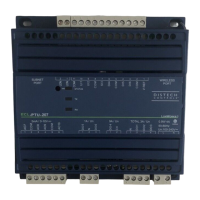
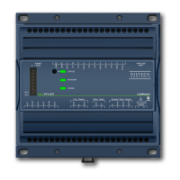
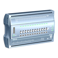
Figure1: ECLYPSE ECY-VAV Controller (left) and ECLYPSE ECY-VAV-PoE Controller (right)
Product Description
This document describes the hardware installation procedures for the ECLYPSE Connected VAV Controller. The ECLYPSE Connected VAV Controller
is designed to control any variable air volume (VAV) box. It supports BACnet/IP communication and is a listed BACnet Building Controller (B-BC). The
Connected VAV Controller comes with an embedded web server that enables web-based VAV application configuration and a visualization interface. It
also features embedded scheduling, alarming, and logging. Control logic and graphic user interface can be customized as required for the application.
The ECLYPSE Connected VAV Controller meets the requirements of VAV zone applications, including: Cooling with Reheat VAV Box & Perimeter Heat-
ing, Parallel Fan VAV Box, Series Fan VAV Box, and Room Pressurization.
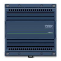
This document describes the hardware installation procedures for the following controllers: ECY-VAV and ECY-VAV-PoE. The related terminal covers
are also covered.
General Installation Requirements
For proper installation and subsequent operation of each controller, pay special attention to the following recommendations:
£ Upon unpacking the product, inspect the contents of the carton for shipping damages.
Do not install damaged modules.
£ Avoid areas where corroding, deteriorating or explosive vapors, fumes or gases may be present.
£ Ensure the mounting surface can support the controller, DIN rail, and any user-supplied enclosure.
£ When installed in an enclosure, select one that provides sufficient surface area to dissipate the heat generated by the controller and by any other
devices installed in the enclosure. A metal enclosure is preferred. If necessary, provide active cooling for the enclosure.
£ The controller’s datasheet specifies the power consumption (amount of heat generated), the operating temperature range, and other environmental
conditions the controller is designed to operate under.
£ Ensure that all equipment is installed according to local, regional, and national regulations.
£ If the controller is used and/or installed in a manner not specified by Distech Controls, the functionality and the protection provided by the controller
may be impaired.
Any type of modification to any Distech Controls product will void the product’s warranty.
Take reasonable precautions to prevent electrostatic discharges to the controller when installing, servicing or
operating the controller. Discharge accumulated static electricity by touching one’s hand to a well-grounded
object before working with the controller.
I n s t a l l a t i o n G u i d e
Question and Answer IconNeed help?

Do you have a question about the Distech Controls ECLYPSE ECY-VAV and is the answer not in the manual?

Distech Controls ECLYPSE ECY-VAV Specifications

General IconGeneral
ModelECY-VAV
TypeVAV Controller
Communication ProtocolBACnet/IP
Input Voltage24 VAC/VDC
Power Consumption5 VA
Outputs2 Analog Outputs
EnclosurePlastic

Summary

Product Description and Installation Requirements

Product Description

Details the hardware installation procedures for the ECLYPSE Connected VAV Controller.

General Installation Requirements

Provides essential recommendations for proper installation and operation of the controller.

Device Markings and Wiring Best Practices

Device Markings and Symbols

Explains various symbols found on the controller and their meanings.

General Wiring Recommendations

Outlines best practices for wiring, including safety and noise prevention.

Module Enclosure Dimensions

ECY-VAV Model Dimensions

Provides detailed dimensions and component identification for the ECY-VAV model.

ECY-VAV-PoE Model Dimensions

Details the enclosure dimensions specific to the ECY-VAV-PoE model.

Controller Dimensions and Configuration Jumpers

Controller Dimensions with Terminal Covers

Shows overall dimensions of ECY-VAV series controllers when terminal covers are attached.

Configuration Jumper Location

Identifies the location of configurable jumpers on the ECY-VAV Series controller.

Mounting Procedures

Mounting Instructions and Position

Guides on controller installation, including orientation for condensation prevention.

Terminal Cover Mounting Procedure

Step-by-step instructions for attaching terminal covers to the VAV controller.

VAV Controller Mounting Procedure

VAV Controller Mounting Procedure

Detailed steps for mounting the controller onto the VAV box damper shaft.

ECY-VAV Model Power Wiring

Power Wiring for ECY-VAV Model

Explains power connection requirements and transformer sizing for the ECY-VAV model.

ECY-VAV Daisy Chain Performance and Wiring

ECY-VAV Daisy Chain Performance

Presents performance data for daisy-chaining multiple ECY-VAV devices.

Daisy-Chain Wiring Best Practices

Provides guidelines for wiring controllers in a daisy-chain configuration.

ECY-VAV Model Power Wiring Diagrams

ECY-VAV Model Power Wiring Diagrams

Illustrates recommended power wiring for ECY-VAV controllers.

ECY-VAV Input Wiring Options

Input Wiring Options

Details various sensor input types and their connection diagrams for the ECY-VAV controller.

ECY-VAV Output Wiring Options

Output Wiring Options

Describes different control output types and their corresponding connection diagrams.

Communications Wiring Overview

Communications Wiring

Information on network topology, cable types, and device identification for BACnet IP.

ECY-VAV Network Connectivity

ECY-VAV Wired Connection

Explains the wired network connection for the ECY-VAV model, including PoE.

Wireless Connection Setup

Guides on setting up a wireless connection to the controller via a Wi-Fi hotspot.

Controller Configuration and Access Methods

Controller Configuration Methods

Outlines various ways to connect and configure the controller's interface.

Connecting via Hostname

Instructions for accessing the controller's web interface using its factory-default hostname.

Connecting via IP Address

Steps for accessing the controller's web interface using its IP address.

Connectivity, Wiring, and Reset Procedures

Web Interface Connection and Security

Details initial connection, password change, and network settings for security.

Subnet and M-Bus Wiring

Information on connecting sensors via SUBNET and M-Bus, including length limits.

Reset Button Functionality

Explains the different actions performed by the controller's reset button.

Maintenance, Disposal, and Compliance

Regular Maintenance

Describes minimal maintenance requirements for the controller.

Product Disposal

Provides information on product disposal according to regulations.

Emissions Compliance

Details FCC compliance for the US and Canadian regulations.

Related product manuals