10 / 16
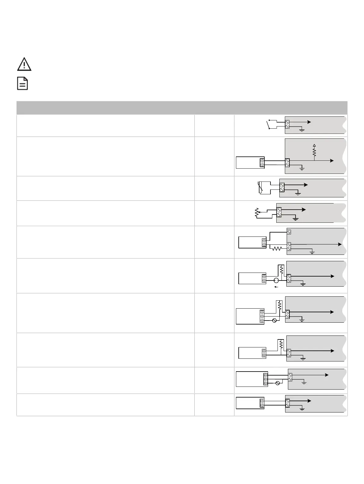
Input Wiring
Input options must be properly configured in EC-
gfx
Program to ensure correct input readings. The table below shows the controller’s available universal
input designation. For terminal block connector wiring best practices, see General Wiring Recommendations [pg.2]. Inputs can be connected as follows.
Before connecting a sensor to the controller, refer to the installation guide of the equipment manufacturer.
£ For a wire length less than 75’ (23m), either a shielded or unshielded 18AWG wire may be used.
£ For a wire up to 200’ (61m) long, a shielded 18AWG wire is recommended.
£ The shield of the wire should be grounded on the controller side only and the shield length should be kept as short as possible.
Sensor Input Type ECY-VAV Input
Designation
Input Connection Diagram
£ Dry Contact input.
£ Pulsed input.
£ UIx
£ DIx
UIx, DIx or SIx
COM
To Digital Input
Digital Dry Contact
NO-NC
£ Pulse input used with a 2-wire sensor powered by its own power source –
this input supports a maximum input frequency of 1Hz (500ms minimum ON/
OFF). Connect the pulse input according to the figure for a pulse meter that
can pull-down a +5VDC supply with a 10KΩ pull-up resistor (Internal supply
type).
£ UIx
£ DIx
Pulse Meter
Output
C
ontroller
P
ulse
Inpu
t
E
quivalent
Circuit
UIx or DIx
COM
To Pulse Count
Accumulator
+
-
10 kവ
+5 VDC
£ RTD input (for example, 1000Ω).
£ Thermistor Input (for example, 10kΩ type II and III).
£ UIx
UIx or SIx
COM
To Analog-To-
Digital Converter
RTD/
Thermistor
£ Resistive input, maximum 350kΩ (for example, use with 10kΩ and 100kΩ
potentiometers).
£ UIx
UIx or SIx
COM
To Analog-To-
Digital Converter
3RWHQWLRPHWHU
Nവ
£ 0 to 20mA input used with a 2-wire, 0 to 20mA sensor powered by the con-
troller’s internal 18VDC power supply.
£ An on-board 18VDC power supply can provide the necessary power for
20mA current loop sensor operation.
£ Connect a 249Ω resistor between the UIx and COM terminals.
£ UIx
+
-
Sensor
0-20mA
UIx
COM
To Analog-
To-Digital
Converter
+18VDC
249Ω / ¼W
£ 0 to 20mA input used with a 2-wire, 0 to 20mA sensor powered by an exter-
nal 24 AC/DC power supply.
£ Connect a 249Ω resistor between the UIx and COM terminals.
£ UIx
-
+
Sensor
0-20mA
UIx
COM
To Analog-To-
Digital Converter
24VDC
249Ω ¼W
£ 0 to 20mA input used with a 3-wire, 0 to 20mA sensor powered by an exter-
nal 24 AC/DC power supply.
£ Connect a 249Ω resistor between the UIx and COM terminals.
When daisy-chaining two or more controllers on one transformer, wire the
controller according to Figure 14.
£ UIx
AC
+
Common
Sensor
UIx
COM
To Analog-To-
Digital Converter
24VAC
0-20mA
249Ω ¼W
£ 0 to 20mA input used with a sensor powered by its own power source.
£ Connect a 249Ω resistor between the UIx and COM terminals.
£ UIx
+
-
Sensor
UIx
COM
To Analog-To-
Digital Converter
0-20mA
249Ω ¼W
£ Voltage input used with a 3-wire 0 to 10VDC or 0 to 5VDC sensor powered
by an external 24 AC/DC power supply.
When daisy-chaining two or more controllers on one transformer, wire the
controller according to Figure 14.
£ UIx
AC
+
Common
0-10V
Sensor
UIx
COM
To Analog-To-
Digital Converter
24VAC
£ Voltage input used with a 0 to 10VDC or 0 to 5VDC sensor powered by its
own power source.
£ UIx
+
-
0-10V
Sensor
UIx
COM
To Analog-
To-Digital
Converter
Table1:
ECY-VAV Input Wiring