5 / 16
The ECY-VAV-PoE Controller must be used with an
IEEE 802.3at
type 2 certified network switch that can supply 25.5 W at the powered device. Each of
the switch’s ports must be configured for static (hardware) power negotiation (that is, Data Link Layer Classification is not supported).
By default, the jumpers for this controller are set to the
IEEE 802.3at 25.5W
position (the factory default setting). With the
IEEE 802.3at
network switch,
the amount of power supplied to the device is set to be automatically negotiated (
Auto
position).
Mounting Instructions
Each controller is specially designed for easy installation either directly on an air duct or in a panel by using the integrated mounting collar and the screw
that is provided with the controller. This mounting arrangement opposes the torque applied to the damper shaft.
If you are installing an ECY-VAV-PoE Model or a controller with terminal covers, see Mounting Procedure for Terminal Covers [pg. 5]. If you are in-
stalling an ECY-VAV Model, see VAV Controller Mounting Procedure [pg.6].
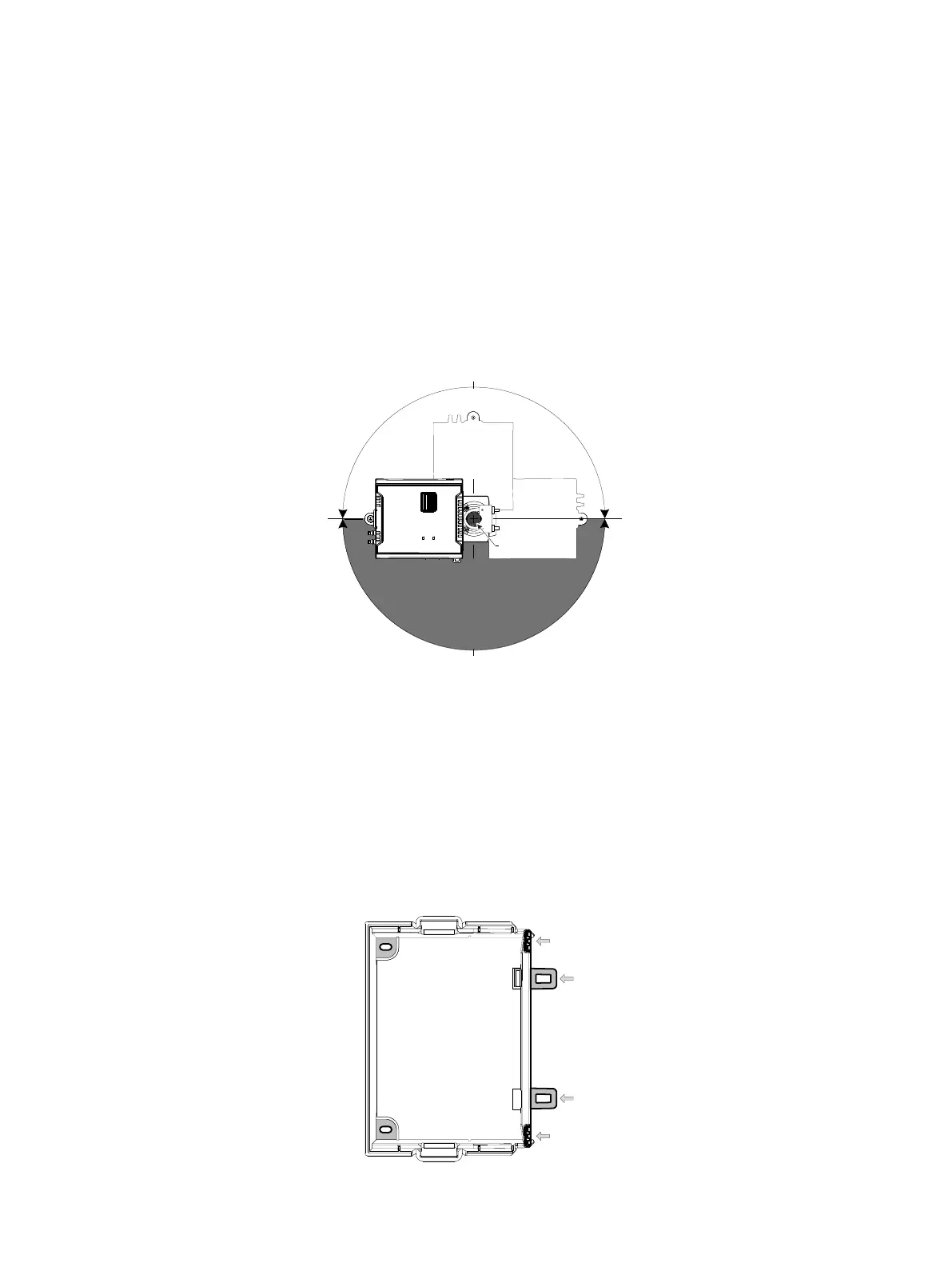
Mounting Position
To prevent condensation on the VAV box’s damper shaft from entering the controller’s electronics, the controller’s mounting orientation should be any
position above the damper shaft (between 0 and 180°) so that any condensation from the damper shaft will fall away from the controller’s electronics.
Further countermeasures may be required in some installations. This is important in hot, humid climates where the VAV box is located near exterior
doors or loading bays that may be blocked open or when the VAV box air supply is below 50°F (10°C).
VAV Box Shaft
0° 180°
90°
270°
Figure7: Recommended Mounting Position Angle Range
Mounting Procedure for Terminal Covers
Terminal covers can be added to any VAV controller to protect inadvertent contact with the controller’s electrical connections.
£ A terminal cover kit can be added to both sides of the controller.
£ The ECY-VAV-PoE models come with a single terminal cover that has internal circuitry which must be installed on the side shown in Figure 4. A
second terminal cover can be added to the other side of the ECY-VAV-PoE model controller; see Figure 5.
Controllers with terminal block covers can only be mounted on a flat surface that is sufficiently large to provide space around the installation. In this sce-
nario, conductors must be made inaccessible and wiring must comply with local wiring regulations and methods appropriate for fixed equipment installa-
tion in a building (the use of cable conduits and trunking for example).
1. Separate the cover from the base of the terminal covers.
2. Attach the base of the terminal cover(s) to the underside of the VAV controller’s body with the tabs shown in Figure 8 .
3. Install the VAV controller according to the next procedure, VAV Controller Mounting Procedure.
Tabs that latch to the VAV controller’s body
Figure8: Terminal Cover Attachment Tabs