2 / 16
Device Markings (Symbols)
Certain markings (symbols) can be found on the controller and are defined as follows:
Symbol Description
CE marking: the device conforms to the requirements of applicable EC directives.
UKCA marking: the device conforms to the requirements of applicable Great Britain regulations.
Products must be disposed of at the end of their useful life according to local regulations.
Read the Hardware Installation Guide for more information.
For indoor use only.
UL marking: conforms to the requirements of the UL certification.
FCC marking: This device complies with FCC rules part 15, subpart B, class B.
Warning Symbol: Significant information required. Refer to the Hardware Installation Guide.
Alternating Current
Direct Current
General Wiring Recommendations
Risk of Electric Shock:
Turn off power before any kind of servicing to avoid electric shock.
£ All wiring must comply with electrical wiring diagrams as well as national and local electrical codes.
£ To connect the wiring to a device, use the terminal connectors. Use a small flat screwdriver to tighten the terminal connector screws once the wires
have been inserted (strip length: 0.25’’ (6mm), maximum tightening torque 0,4 Nm (3.45 in-lb)).
£ Comply with all network and power supply guidelines outlined in the Network Guide.
£ Keep wiring separate according to their function and purpose to avoid any ambient noise transmission to other wires. Use strapping to keep these
wires separated. For example, keep power, hazardous voltage, SELV, PELV, network, and input wiring separate from each other.
£ Power cables must be between 18 and 14 gauge (0.82 to 2.1mm
2
cross-sectional area). When connecting one wire to a controller’s terminal block
clamping cage (pole), the wire must be between 22 and 14 gauge (0.33 and 2.1mm
2
cross-sectional area). When connecting two wires to a con-
troller’s terminal block clamping cage, both wires must be the same thickness, both wires must be between 22 and 16 gauge (0.33 to 1.3mm
2
cross-
sectional area), and both wires must be of the same type (solid or stranded). Twist the wires together and insert then into the controller’s terminal
block clamping cage. For any other wiring combination (mixed wire thickness, mixed solid and stranded conductors, more than three wires, wire
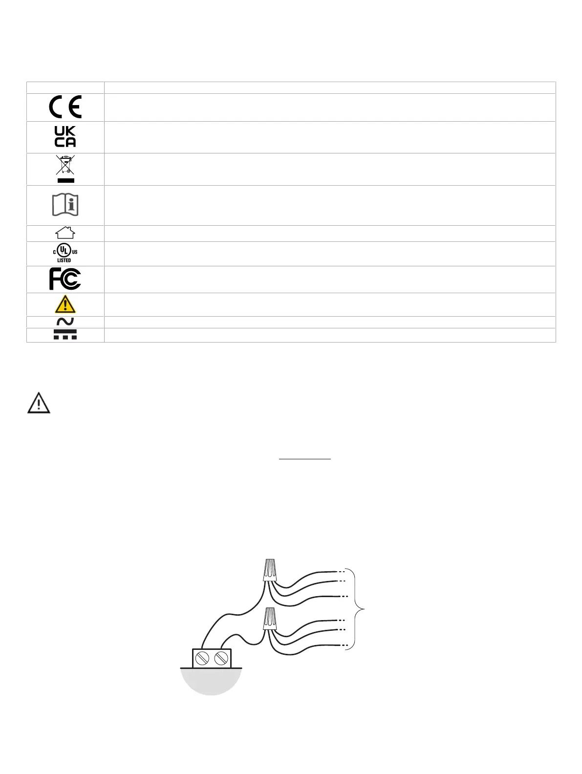
thickness is out of range), twist the wires together and use a wire nut and a pig tail to connect to the controller’s terminal block connector as show
below.
Controller
Wire Nuts
Terminal Block
Connector
Wire Connections
Pigtails
Figure2: Using a Wire Nut and Pigtail to Wire the Controller
£ Keep input and output wiring in conduits, trays or close to the building frame if possible.