EasyManua.ls Logo

Distech Controls ECL/ECB-PTU Series - User Manual

Distech Controls ECL/ECB-PTU Series
138 pages
Print Icon
To Next Page IconTo Next Page
Loading...
User Guide
Network Guide

Table of Contents

Questions and Answers

  • K
    Kyle DanielsAug 14, 2025
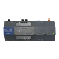
    Why is my Distech Controls Controller not turning on even though it's powered?
    • D
      Dr. Mark BaxterAug 14, 2025
      If your Distech Controls Controller is receiving power but not turning on, there could be a few reasons. Here's what to check: * **Blown Fuse:** If it's a 24V controller, the fuse may have blown. Disconnect the power, check the fuse, and reconnect the power. * **Power Supply Polarity:** Make sure that consistent polarity is maintained between all controllers and the transformer. Ensure the COM terminal of each controller is connected to the same terminal on the secondary side of the transformer. * **Insufficient Power:** If it's a 24V controller, the transformer may not be powerful enough. Verify that the transformer used is powerful enough to supply all controllers.
  • N
    Nathan DeanAug 18, 2025
    What to do if Distech Controls ECL/ECB-PTU Controller wireless devices are not working correctly?
    • C
      christinebrownAug 19, 2025
      If wireless devices associated with your Distech Controls Controller aren't functioning as expected, consider the following troubleshooting steps: * **Device Association:** Verify that the device is associated with the controller using the device configuration wizard. * **Power:** Recharge the device with light if it's solar-powered, or replace the battery if it's battery-powered. Also, ensure sufficient light intensity (200lx for 4 hours/day) for solar-powered devices. * **Distance:** Reposition the device to ensure it's within range of the Wireless Receiver. * **Configuration:** Check the device configuration using EC-gfxProgram to ensure it's enabled.
  • W
    waynebyrdAug 27, 2025
    What does it mean if the STATUS LED is blinking on Distech Controls ECL/ECB-PTU Controller?
    • S
      Sara BarberAug 27, 2025
      If the STATUS LED on your Distech Controls Controller is blinking, it indicates that the device has detected a fault condition. Consult the fault codes table for more information.
  • S
    Stephanie WebbOct 31, 2025
    What to do if Distech Controls ECL/ECB-PTU Controller does not communicate on a large network?
    • B
      Becky PatrickNov 1, 2025
      If your Distech Controls Controller communicates well over a short network but fails on a larger one, consider these potential issues: * **Network length:** Ensure the total wire length does not exceed the specifications outlined in the Network Guide. * **Wire type:** Verify the wire type matches the specifications in the Network Guide. * **Network wiring:** Double-check all wire connections to ensure they are correct. * **Network termination:** Check the network terminations, as incorrect or broken terminations can affect communication integrity based on the controller's position on the network. * **Number of controllers:** Ensure the number of controllers on a channel does not exceed 50. If it does, use a router or a repeater. * **Max Master parameter:** Configure the maximu...
  • K
    Kelly AndersonNov 5, 2025
    What to do if Distech Controls ECL/ECB-PTU hardware output is not operating correctly?
    • G
      gbeckerNov 5, 2025
      If a hardware output on your Distech Controls Controller isn't working correctly, consider the following: * **Blown Fuse:** If it's a 24V controller with an auto-reset fuse, disconnect the power and output terminals, wait a few seconds for the fuse to cool down, check the power supply and output wiring, and then reconnect the power. * **Wiring Issues:** Verify the output wiring is correct, referring to the module's hardware installation manual and the peripheral device's manufacturer specifications. * **Configuration Problems:** Use EC-gfxProgram to check the output configuration to ensure it is enabled. * **Actuator Problems:** If using a 0-10V output with a 24VAC powered actuator, check the polarity of the 24VAC power supply connected to the actuator. Reverse the 24VAC wire if n...
  • L
    lmartinezNov 9, 2025
    What to do if Distech Controls ECL/ECB-PTU Controller hardware input is not reading the correct value?
    • R
      Robert BrownNov 9, 2025
      If a hardware input on your Distech Controls Controller isn't reading the correct value, here's what to check: * **Wiring:** Ensure the wiring is correct, following the module's hardware installation manual and the peripheral device's manufacturer's recommendations. * **Circuits:** Use a voltmeter to check the voltage on the input terminal. For a digital input, a short circuit should show approximately 0V, while an open circuit should show approximately 5V. Correct the wiring if there's a fault. * **Configuration:** Verify the input configuration using the controller configuration wizard. * **Voltage/Current:** An over-voltage or over-current at one input can affect other input readings. Ensure you're respecting the allowed voltage/current range limits for all inputs. Check the ap...
  • T
    Travis TownsendNov 22, 2025
    What to do if Distech Controls ECL/ECB-PTU device does not communicate on the BACnet MS/TP network?
    • S
      Sheila MurphyNov 22, 2025
      If your Distech Controls Controller isn't communicating on the BACnet MS/TP network, consider these potential causes: * **Voltage Issues:** For 24V controllers, check for 'Poor-Quality Power' status, verify the power supply voltage is within 24VAC/DC ±15%, and check for tripped fuses or circuit breakers. * **Transformer Overload:** For 24V controllers, check for 'Poor-Quality Power' status and ensure the transformer is powerful enough. * **Wiring:** Double-check wire connections. * **Termination:** Check network terminations. * **Max Master Parameter:** Configure the Max Master to the highest MAC Address of any device on the MS/TP data bus. * **Duplicate MAC Address:** Ensure each controller has a unique MAC Address. If the MAC Address DIP switch is set to 0 (all off), use an ...

Summary

CHAPTER 1 Introduction

About This User Guide

Overview of the guide's purpose, intended audience, and conventions used.

Acronyms and Abbreviations

Definitions of technical terms and abbreviations used throughout the document.

CHAPTER 2 BACnet MS;TP Communication Data Bus Fundamentals

BACnet MS;TP Data Transmission Essentials

Core principles of BACnet MS/TP data transmission, including polarity and electrical characteristics.

Maximum Number of BACnet MS;TP Devices and Baud Rate

Limits on devices, baud rates, and device loading for MS/TP data bus segments.

Data Bus Topology and EOL Terminations

Explains acceptable topologies and the function of End-of-Line terminations for data bus integrity.

Data Bus Shield Grounding Requirements

Essential procedures for grounding data bus shields to prevent electromagnetic interference.

Device Addressing

Methods for assigning unique MAC addresses and Device Instances to network devices.

Power Supply Requirements for 24 V Controllers

Critical considerations for supplying power to 24V controllers, including ground lift.

CHAPTER 3 LonWorks Communication Bus Fundamentals

TP;FT 10 Network Topologies

Details different TP/FT 10 network topologies (Bus, Free) and their wiring requirements.

Extending the Network

Methods for extending network range using repeaters or routers to overcome distance limitations.

Grounding a Network

Guidelines for grounding LonWorks shielded twisted pair cables to ensure signal integrity.

Power Supply Requirements for 24 V Controllers

Essential power supply considerations for LonWorks 24V controllers, including transformer selection.

CHAPTER 4 Subnetwork Installation Guidelines

Subnetwork Module Compatibility and Supported Quantity Charts

Lists module compatibility and maximum quantities allowed per controller model.

Cat 5 e Cable Subnetwork Data Bus Cable Requirements

Specifies physical specifications and cable requirements for Cat 5e subnetwork data bus.

Setting the Subnet ID Addressing for Room Devices

Explains how to configure unique subnet ID addresses for various room devices.

CHAPTER 5 Controller Installation and Maintenance Tasks with an Allure EC-Smart-Vue Sensor

Commissioning a Controller with an Allure EC-Smart-Vue Sensor

Guides on commissioning controllers using the Allure EC-Smart-Vue sensor for setup.

Setting the Baud Rate for ECB-Series Controllers

Instructions for optionally setting the baud rate for ECB controllers for network optimization.

CHAPTER 6 BACnet Troubleshooting

Troubleshooting ECB Device Symptoms

Lists common symptoms, causes, and solutions for diagnosing ECB device operational issues.

CHAPTER 7 LonWorks Troubleshooting

Troubleshooting ECL Device Symptoms

Lists common symptoms, causes, and solutions for diagnosing ECL device operational issues.

CHAPTER 8 ECx-4 XX Series I;O Extension Module Specific Troubleshooting

Troubleshooting ECx-4 XX Series I;O Extension Module Device Specific Symptoms

Addresses specific troubleshooting steps for ECx-4XX I/O Extension Modules.

CHAPTER 9 Allure EC-Smart-Vue Sensor Troubleshooting

Troubleshooting Allure EC-Smart-Vue Sensor Symptoms

Provides solutions for common symptoms and error codes related to the Allure EC-Smart-Vue sensor.

CHAPTER 10 ECx-Light;Blind Series Troubleshooting

Troubleshooting ECx-Light; Blind Series Symptoms

Offers solutions for common issues related to ECx-Light/Blind series expansion modules.

APPENDIX A Typical BACnet EIA-485 Data Bus Transmission Example

EIA-485 Signal Specifications

Details electrical signal specifications for EIA-485 communication, including voltage levels.

APPENDIX B How to Set a Dip Switch

APPENDIX C Metric Conversions for Wire Gauge

Distech Controls ECL/ECB-PTU Series Specifications

General IconGeneral
BrandDistech Controls
ModelECL/ECB-PTU Series
CategoryController
LanguageEnglish

Related product manuals