54 Network Guide
TP/FT 10 Network Topologies
The physical routing of the communication channel defines the network topology. The channel
and transceiver types define the requirements and limitations of each wiring topology.
TP/FT 10 network segments require termination for proper data transmission performance.
Free topology and bus network topology differ in their termination requirements. The following
sections describe the various network topologies, their terminator types and termination pro-
cedures.
Bus Topology
A bus topology is a physical routing of the communication channel that includes a distinct
beginning and end. It is also known as a daisy-chain topology.
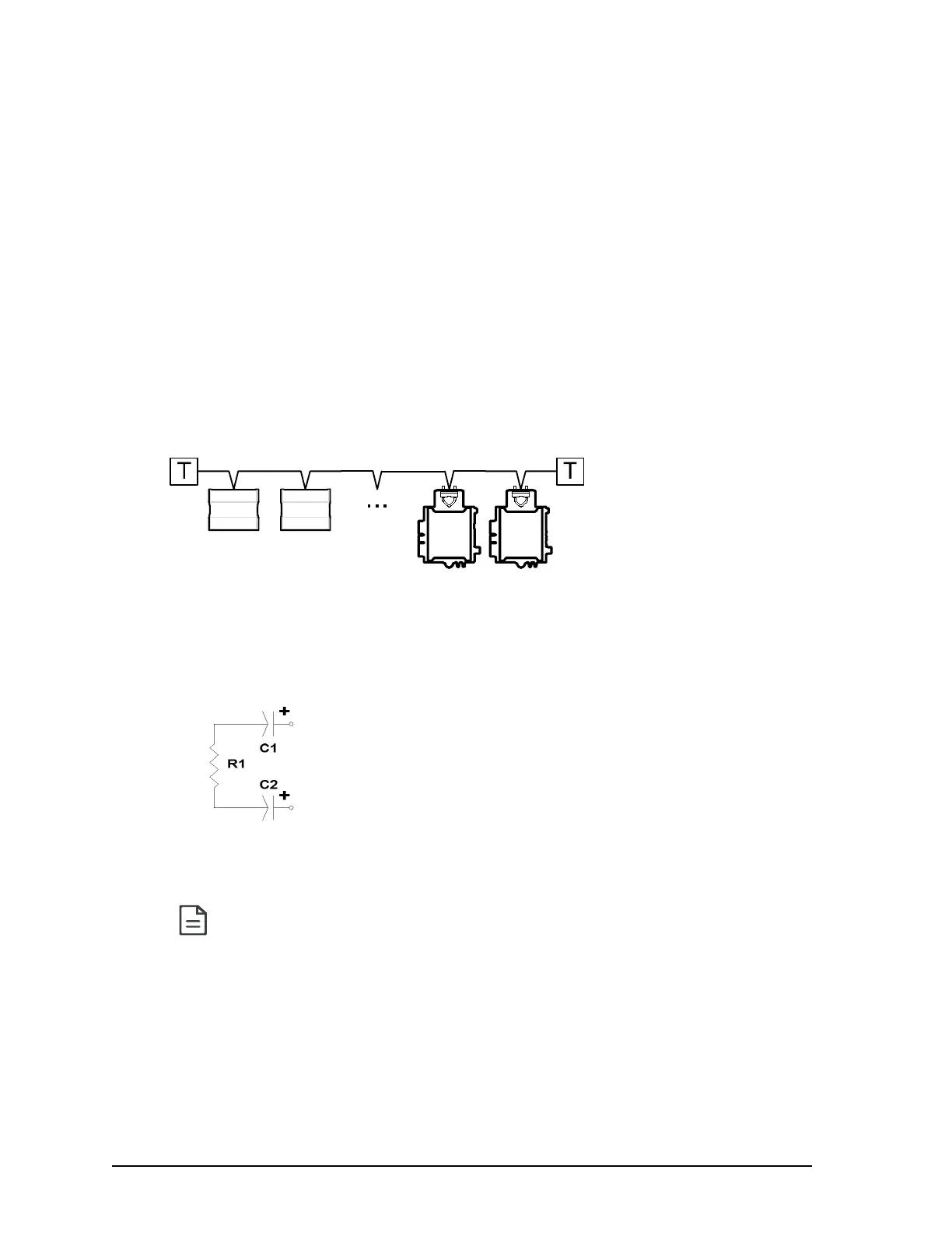
Figure 32: Figure 3 3: Bus Topology
TP/FT 10 Bus Topology Network Termination
For bus topology type networks, use the following terminators at each end of the bus topology
channel (2 terminators per channel in total):
R1 = 105Ω, ±1%, ⅛W
C1 = 100µF, ≥50V
C2 = 100µF, ≥50V
It is recommended to use a bus topology when designing a network. Bus topologies
are the easiest to troubleshoot and the maximum wiring length in a bus topology is
greater than that for a free topology. See Network Cables on page 55 for detailed
information about wiring lengths and network cable considerations.