15 / 16
Connecting to the Controller’s Configuration Web Interface
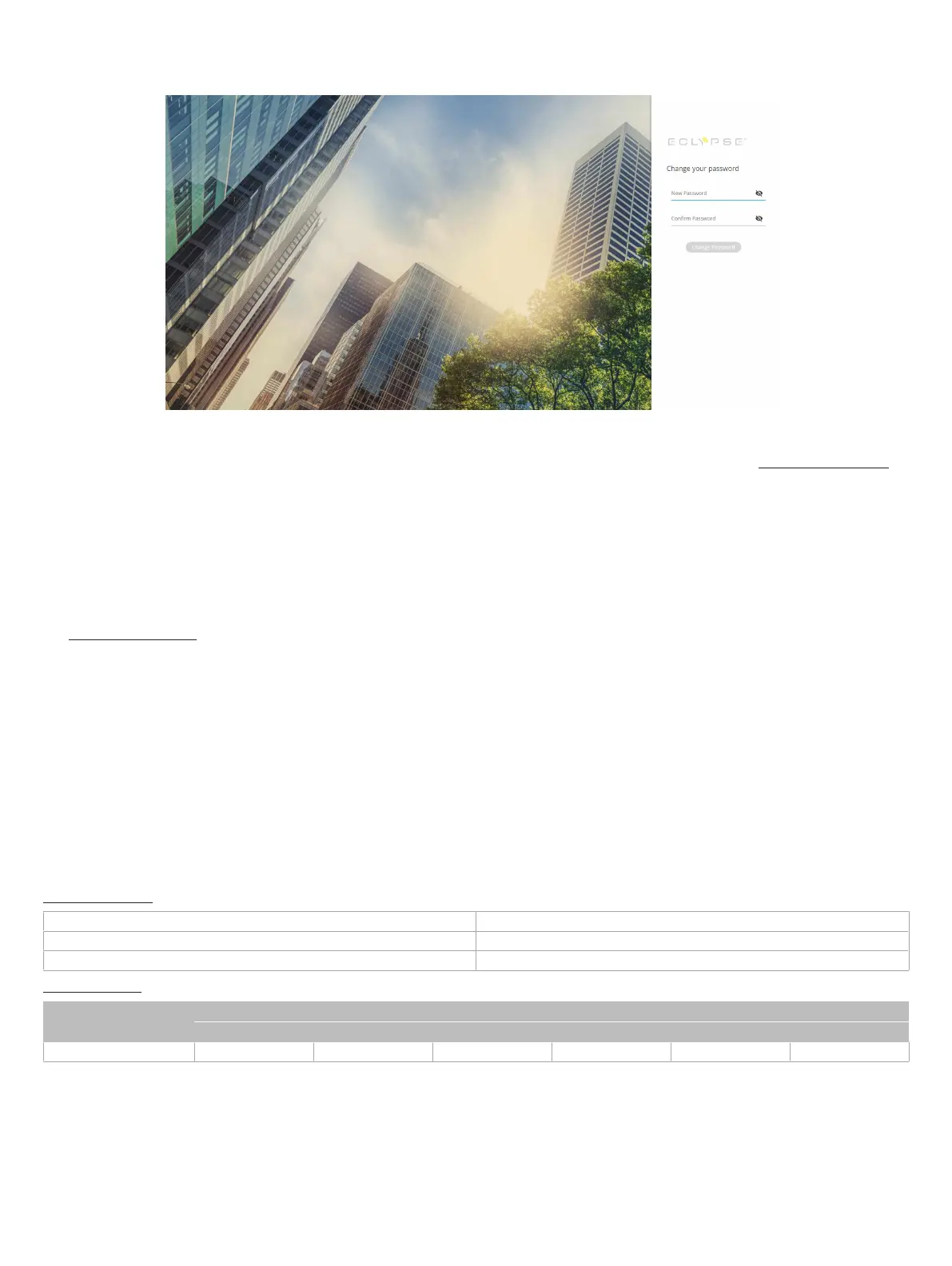
At the first connection to an ECLYPSE Controller you will be forced to change the password to a strong password for the admin account to protect ac-
cess to the controller.
In Network Settings, configure the controller’s network parameters so that they are compatible with your network. See the ECLYPSE User Guide for
more information about network settings and how to secure the controller. It is important to create new user accounts with strong passwords to protect
the controller from unauthorized access. Remove the factory default admin account as this is a commonly known security breech (only the password for
this user account needs to be compromized).
Subnet Wiring
Supported Allure Series communicating sensors are connected to the
SUBNET
port modular connector of the controller with a standard Category 5e
Ethernet patch cable fitted with RJ-45 connectors.
The ECLYPSE User Guide provides extensive information and requirements for the connection of an Allure series communicating sensor. It contains in-
formation about network topology and length, cable type, setting the Subnet ID, etc. It can be downloaded from our website. See also the Hardware In-
stallation Guide supplied with the Allure series communicating sensor.
M-Bus Communications Wiring
M-Bus communications are made by connecting meters directly in an M-Bus port.
The ECY-VAV integrates one M-Bus port when connected to an ECY-MBUS extension module via a USB connection.
The M-Bus port must be configured in EC-
gfx
Program prior to use. M-Bus meters are integrated into EC-
gfx
Program using the M-Bus device block.
Maximum M-Bus Device Wiring Length
The following information provides wiring limitations for M-Bus devices. The wiring length provided below was tested as a worst-case scenario with all
meters being located at the end of the bus. If meters are more evenly spaced along the bus, then the maximum wiring length can possibly be increased.
Testing Conditions:
Current per slave/meter 1.5 mA
Max ∆V accepted on the bus 2 V
Cable capacity 110 nf/km
USB Connection:
M-Bus Meters AWG 15 AWG 22
300 Bps 2400 Bps 9600 Bps 300 Bps 2400 Bps 9600 Bps
3 12000 m (39370 ft) 4500 m (14763 ft) 2400 m (7874 ft) 4000 m (13123 ft) 2200 m (7217 ft) 1150 m (3773 ft)
Table2:
Maximum Wiring Length from the Controller to the Last M-Bus Meter on USB connection
Using the Reset Button
The reset button is located under the controller’s cover (see Figure 6). Depending on the amount of time the reset button is held down, different actions
are taken by the controller. The STATUS LED will turn off after each time interval. See Figure 6 for status LED indicator location.