EasyManua.ls Logo

Distech Controls ECB-PTU Series User Manual

Distech Controls ECB-PTU Series
24 pages
To Next Page IconTo Next Page
Page #1 background imageLoading...
Page #1 background image
ECB-PTU Series
Product Description
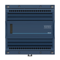
This document describes the hardware installation procedures for the ECB-PTU Series BACnet controllers.
The Distech Controls ECB-PTU Series controllers are designed to control and monitor powered terminal units such as powered fan coil units, heat
pumps, chilled ceilings and small air handling units.
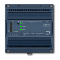
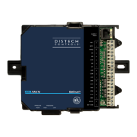
This product line includes the following controllers: ECB-PTU-107, ECB-PTU-207, ECB-PTU-208, ECB-PTU-307, and ECB-PTU-308.
The ECB-PTU Series are compatible with the ECx-Light/Blind lighting and sunblind expansion modules (refer to the ECx-Light/Blind Series Expansion
Modules Hardware Installation Guide).
Each controller uses the BACnet® MS/TP LAN communication protocol.
This document describes the hardware installation procedures for the following controllers: ECB-PTU-107, ECB-PTU-207, ECB-PTU-208, ECB-PTU-307
and ECB-PTU-308.
These controllers are all built on a similar platform but have different numbers of inputs and outputs. Moreover, each
individual model has different amounts of digital and/or analog outputs. For more information on the specific layout
and functionality of each controller, please refer to their individual datasheets and user guides.
General Installation Requirements
For proper installation and subsequent operation of the device, pay special attention to the following recommendations:
£ It is recommended that the controller(s) be kept at room temperature for at least 24 hours before installation to allow any condensation that may
have accumulated due to low temperature during shipping/storage to evaporate.
£ Upon unpacking, inspect the contents of the carton for shipping damages.
Do not install a damaged device.
£ The controller should be installed in an appropriate ventilated enclosure with minimum dimensions 240 x 240 x 100 mm.
£ Avoid areas where corroding, deteriorating, or explosive vapors, fumes or gases may be present.
£ Allow for proper clearance around the controller’s enclosure, wiring terminals, and service pin, in order to provide easy access for hardware configu-
ration, and in order to ventilate the heat generated by the controller.
£ Orient the controller with the ventilation slots towards the top to permit proper heat dissipation. When installed in an enclosure, select one that pro-
vides sufficient surface area to dissipate the heat generated by the controller and by any other devices installed in the enclosure. A metal enclosure
is preferred. If necessary, provide active cooling for the enclosure.
£ The device’s datasheet specifies the power consumption (amount of heat generated), the operating temperature range, and other environmental
conditions the device is designed to operate under.
£ Ensure that all equipment is installed according to local, regional, and national regulations.
I n s t a l l a t i o n G u i d e
Questions and Answers:

Distech Controls ECB-PTU Series Specifications

General IconGeneral
BrandDistech Controls
ModelECB-PTU Series
CategoryController
LanguageEnglish

Summary

Product Description and Requirements

General Installation Requirements

Recommendations for proper installation, including temperature, unpacking, enclosure, and clearances.

Device Markings

Explains common symbols found on devices, their meanings, and certifications.

Installation Procedures

General Wiring Recommendations

Guidelines for safe and effective wiring, including power, network, and signal connections.

Mounting Instructions

Details on how to mount the controllers, including DIN rail and wall mounting methods.

Device Dimensions

Physical dimensions of the controller, shown in front and side views.

Controller Wiring

Power Wiring

Information on voltage, consumption, and required circuit breaker/fuse protection.

Input Wiring

Configuration and connection methods for various input types (Digital, Voltage, Resistive, Pulse).

Output Wiring

Details on wiring analog, digital relay, and triac outputs for different applications.

Communications Wiring

Requirements for BACnet MS/TP network setup, cable type, and polarity.

Commissioning and Configuration

Setting the Allure EC Smart Vue Subnet ID

Steps to configure the Subnet ID on the EC-Smart-Vue sensor for commissioning.

Commissioning ECB-PTU Series Controllers

Procedure to set the controller's BACnet MAC Address using the EC-Smart-Vue sensor.

Setting the BAUD Rate

How to set or automatically detect the BAUD rate for BACnet MS/TP communication.

Wireless and Accessories

Wireless Installation

Connecting wireless devices to the controller via a Wireless Receiver.

Strain Relief and Terminal Block Cover

Installation and removal of strain relief and terminal block covers for wiring management.

Disposal and Compliance

Disposal

Information on product disposal according to WEEE Directive and local regulations.

FCC Statement

FCC compliance statement regarding digital device emissions and interference.

Complementary Information

Additional technical data, EMC immunity, and product repair information.

Wiring Diagrams

Typical ECB-PTU-107 Wiring Diagram

Detailed wiring diagram for the ECB-PTU-107 model, showing inputs and outputs.

Typical ECB-PTU-207 Wiring Diagram

Detailed wiring diagram for the ECB-PTU-207 model, showing inputs and outputs.

Typical ECB-PTU-208 Wiring Diagram

Detailed wiring diagram for the ECB-PTU-208 model, showing inputs and outputs.

Typical ECB-PTU-307 Wiring Diagram

Detailed wiring diagram for the ECB-PTU-307 model, showing inputs and outputs.

Typical ECB-PTU-308 Wiring Diagram

Detailed wiring diagram for the ECB-PTU-308 model, showing inputs and outputs.

Troubleshooting Guide

Controller Power Issues

Troubleshooting steps for when the controller does not turn on, checking fuses and power.

Network Communication Problems

Diagnosing issues with BACnet MS/TP network communication, wiring, and addressing.

Input/Output Operation Issues

Resolving problems with hardware inputs not reading correctly or outputs not operating.

Wireless Device Issues

Troubleshooting common problems with wireless devices not associating or communicating.

Related product manuals