10 / 24
Communications Wiring
The Network Guide provides extensive information and requirements to implement a BACnet MS/TP network. It contains information about network and
sub network length, cable type, device addressing, etc. It can be downloaded from our website. For optimal performance, use Distech Controls 0.5 mm²
(24 AWG) stranded, 3-wire shielded cable or refer to the Network Guide for cable specification. The BACnet MS/TP communication wire is polarity sensi-
tive and the only acceptable topology is to daisy-chain the cable from one controller to the next.
£ The first and last daisy-chained BACnet MS/TP device must have its EOL resistors enabled / installed. All other devices must
have their EOL resistor disabled (default factory setting).
£ When the BACnet MS/TP data bus is connected to a following device, twist data bus shields together.
£ Isolate all shields with electrical tape so there is no exposed metal that can touch ground or other conductors.
£ The shield of the data bus must be connected to the electrical system ground at only one point – usually at one end of the bus
as shown below.
£ Connect no more than 50 devices to a BACnet MS/TP data bus.
£ Use a 2-conductor shielded cable, and connect it as shown on the wiring diagram.
– 2 conductors for data transmission through differential voltage
– Shield connected to the controller’s COM terminal to provide a signal reference. The shield of the data bus must be con-
nected to the electrical system ground at only one point – usually at one end of the bus as shown below.
The controller’s EOL termination is defined by setting the last two pins, marked EOL, of the DIP switch located on the faceplate:
£ If both pins are set to 0, the EOL resistor is disabled.
£ If both pins are set to 1, the EOL resistor is enabled.
If inserting multiple wires in the terminals, ensure to properly twist wires together prior to inserting them into the terminal connectors.
For more information and detailed explanations on network topology and wire length restrictions, refer to the Network Guide, which can be downloaded
from our website.
Device Addressing
The Network Guide provides extensive information and requirements to implement a BACnet MS/TP network. It contains information about network plan-
ning and MAC Address numbering schemes. It can be downloaded from the
www.distech-controls.com
website.
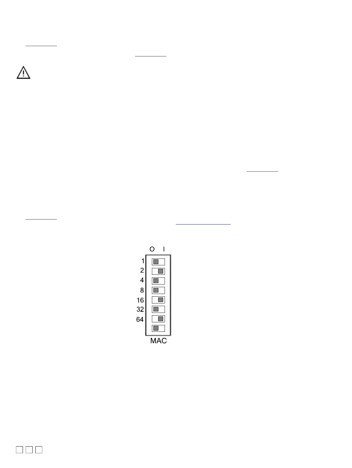
The MAC Address must be set according to your network planning document by setting the DIP switch located on the faceplate or when this DIP switch
is set to 0 (all off), the MAC address can be set by connecting an Allure EC-Smart-Vue sensor to the controller. An example of how to set the device’s
MAC Address DIP switch is shown below.
ON
Must be set to the
OFF (0) position
Figure22:
Typical Device MAC Address DIP Switch Set to 82
The address is the sum of the numbers set to ON. For example, if the second (2), fifth (16), and seventh (64) DIP switches are set to ON, the device
MAC address is 82 (2 + 16 + 64). Only addresses from 1 to 127 are recommended to be used.
The controller must be power cycled after the MAC address DIP switch has been changed. The device instance (DevID) is automatically configured
when setting the MAC Address to prevent network address conflict. The following formula is used to determine the device instance:
DevID = 364 * 1000 + MAC
For example:
MAC: 37
DevID = 364 * 1000 + 37 = 364037
The Device Instance can be changed once the controller has been commissioned through the network management software interface.
 Loading...