5 / 24
Power Wiring
Voltage
:
100-240 VAC; -15%/+10%; 50/60 Hz
Overvoltage Category II - 2.5 kV
Model Typical Consumption Max. Consumption
ECB-PTU-107 < 0.9 W + all external loads 4.0 A
ECB-PTU-207 < 0.9 W + all external loads 4.0 A
ECB-PTU-208 < 2.6 W + all external loads 3.5 A
ECB-PTU-307 < 0.9 W + all external loads 4.0 A
ECB-PTU-308 < 2.6 W + all external loads 3.5 A
Table1:
ECB-PTU Controllers consumption
ECB-PTU-107 4.0 A external circuit breaker type C or 4.0 A fast acting high breaking external fuse (250 VAC min)
ECB-PTU-207 4.0 A external circuit breaker type C or 4.0 A fast acting high breaking external fuse (250 VAC min)
ECB-PTU-208 4.0 A external circuit breaker type C or 4.0 A fast acting high breaking external fuse (250 VAC min)
ECB-PTU-307 4.0 A external circuit breaker type C or 4.0 A fast acting high breaking external fuse (250 VAC min)
ECB-PTU-308 4.0 A external circuit breaker type C or 4.0 A fast acting high breaking external fuse (250 VAC min)
Table2:
ECB-PTU Controllers protection
The controller must be connected to the mains using the provided detachable connector.
The Network Guide provides extensive information and requirements for powering a controller that uses a BACnet network for communications. It can be
downloaded from our website.
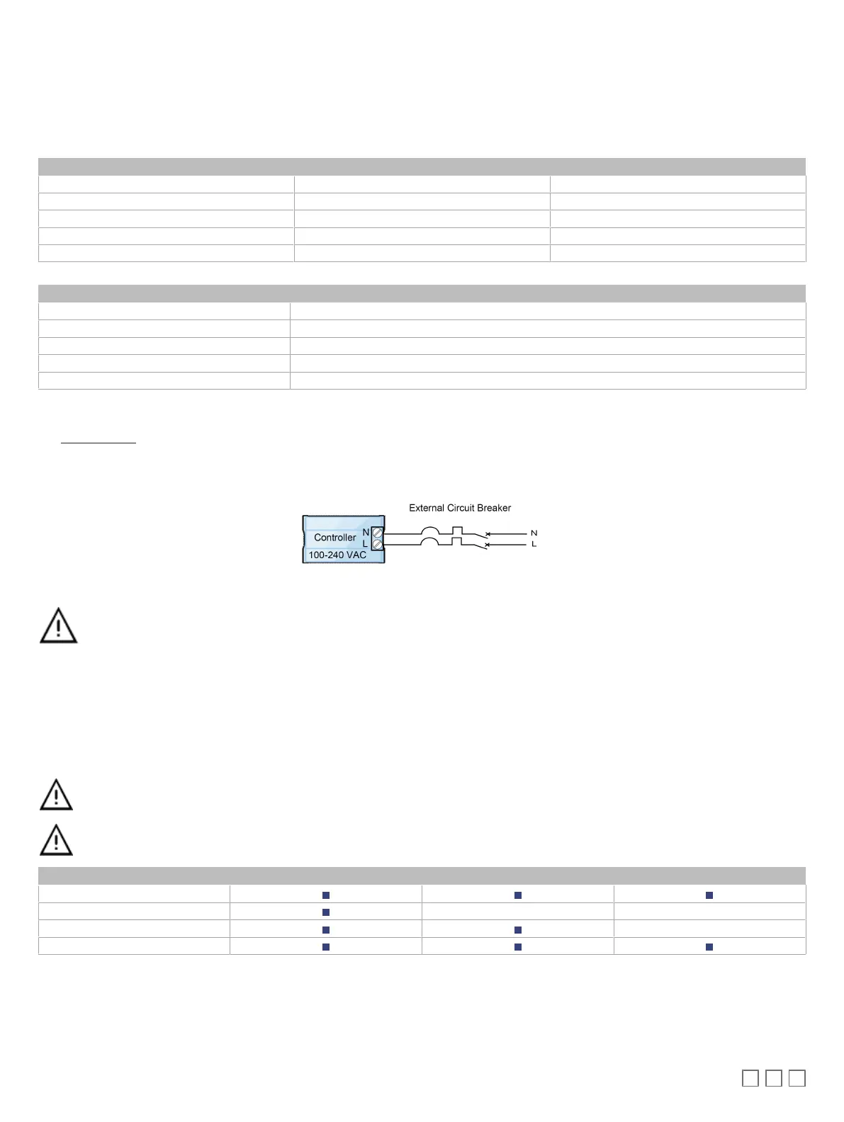
Use an external circuit breaker/fuse on the mains to protect the module against power line spikes. The circuit breaker must be located close to the con-
troller.
Figure5:
Power wiring
The power wires must remain between 1 mm² (17 AWG) and 1.5 mm² (16 AWG). Make sure the cable performances suit the connected
loads.
Operating, handling, or servicing this product must be achieved by a qualified operator. Turn off power before any kind of servicing.
Input Wiring
Each controller has physical connections for six (6) inputs (marked as UIx for Universal Inputs, DIx for Digital Inputs, and SIx for Sensor Inputs). All in-
puts must be configured properly in EC-
gfx
Program to ensure proper input readings.
All input wiring must be connected using the provided detachable connectors.
Before connecting a sensor to the controller, refer to the installation guide of the equipment manufacturer.
Connectors allow the use of cables up to 1.5 mm² (16 AWG).
UI SI DI
Digital Inputs
Voltage Inputs
Resistive Inputs
Pulse Inputs
Table3:
Input Configuration Capabilities