14 / 24
Wireless Installation
When connected to a Wireless Receiver, controllers can receive input signals from a wide selection of wireless devices. Compatible wireless devices in-
clude temperature sensors, duct sensors, window/door contacts and light switches. These devices are easy to install, and can be mounted on a wide
range of building materials.
The Wireless Receiver is available in 315 MHz or 868.3 MHz frequencies.
Before connecting any wireless equipment to the controller, refer to the Open-to-Wireless Application Guide.
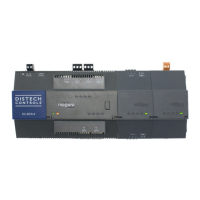
Connecting the Wireless Receiver
The Wireless Receiver is connected to the controller using a 2m (6.5ft) telephone cable with 4P4C modular connectors at both ends. Do not exceed this
cable length. The Wireless Receiver’s telephone socket is located inside the device. To locate it, open the Wireless Receiver by separating its front and
back plates.
Figure23:
Location of the Wireless Receiver’s telephone socket
Connecting to the Controller’s Wireless Port
Each controller has a wireless port in which one end of the Wireless Receiver’s telephone cable plugs in.
Strain Relief and Terminal Block Cover
In certain jurisdictions, terminal block covers are required to meet local safety regulations. Strain reliefs and terminal block covers are available for con-
trollers housed in large enclosures and are used to relieve tension on the wiring and conceal the controllers’ wire terminals. Strain reliefs and terminal
block covers are optional and are sold as peripherals. Strain relief and terminal block covers usage does not comply with DIN rail mounting.
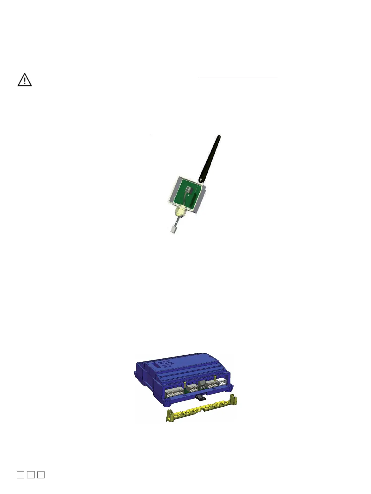
Installing the strain relief and terminal block cover
Prior to connecting all wires, it is recommended to install the strain relief. Two screws are provided for its installation under the bottom part of the enclo-
sure as shown below.
Figure24: Installing the strain relief

 Loading...