9 / 16
24 V AC
24 V COM
Transformer
Fuse: 4 A Max.
Fast Acting
Electrical System Ground –
At Transformer Only
!
Controller 2
AC24 VAC
24 V AC
24 V COM
Controller 1
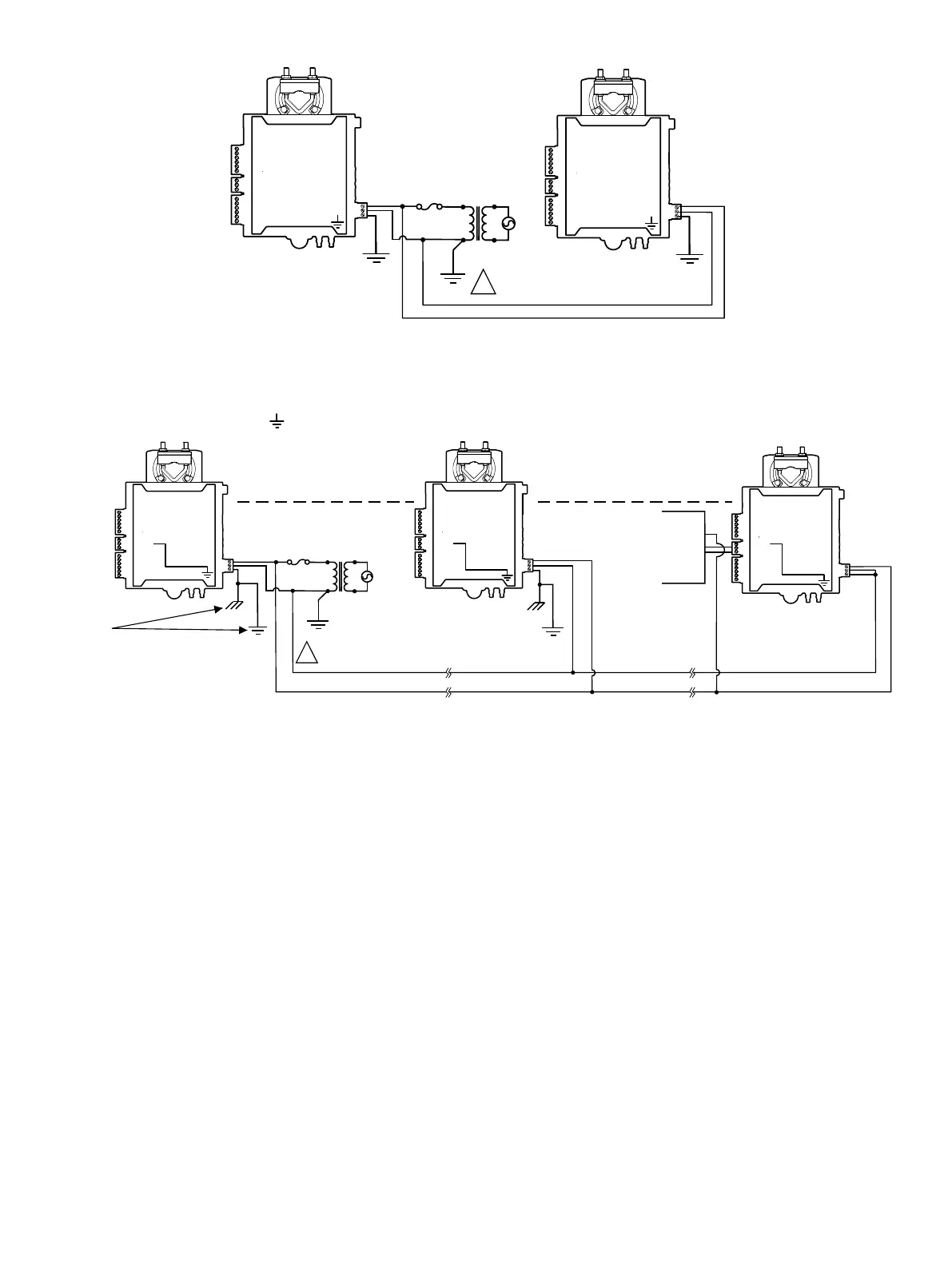
Figure14: ECY-VAV Model Power Wiring
The following diagram shows the recommended wiring of the ECY-VAV Controller with and without a 3-wire peripheral. This configuration applies either
to a daisy-chain configuration or configuration with separate transformers. Note that internally the COM terminals are no longer connected to the 24VAC
COM terminal but rather to the ground ( ) terminal.
Transformer
Electrical System Ground –
At Transformer Only
!
Fuse: 4 A Max.
Fast Acting
OR
Chassis or
Earth Ground
Without 3-wire
peripheral
24V AC
24V COM
0 – 10V
With 3-wire
peripheral
AC24 VAC
UO 6
COM
UO 5
24 V AC
24 V COM
COM
UO 5
24 V AC
24 V COM
UO 6
COM
UO 5
24 V AC
24 V COM
Figure15: ECY-VAV Model Power Wiring With and Without 3-Wire Peripherals