6/12
Output Wiring
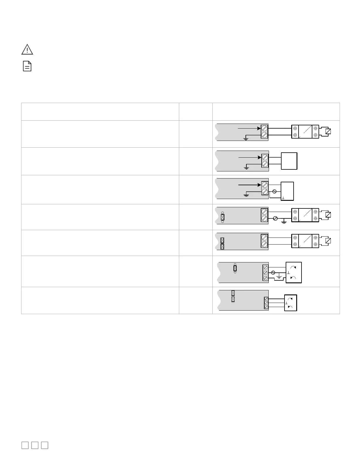
Table 3 shows the available output wiring methods.
Before connecting an output device (actuator, relay, etc.) to the controller, refer to the datasheet and installation guide of the equipment
manufacturer.
For a wire length less than 75’ (23m) long, either a shielded or unshielded 18AWG wire may be used.
- For a wire length up to 200’ (61m) long, a shielded 18AWG wire is recommended.
- The shield of the wire should be grounded on the controller side and the shield length should be kept as short as possible.
- For relay outputs (DOx); select appropriately-sized wiring suitable to the current load.
Table 3: Output Wiring
Output Connection Diagram
Discrete 0 or 12VDC digital, Pulse, or PWM output controlling a
relay.
UOx
From
Digital
Output
12VDC Relay
A1
A2
UOx
COM
Linear 0 to 10VDC digital to analog output.
UOx
0
-10
V
Common
From Digital-
To
-Analog
Output
UOx
COM
0 to 10VDC voltage output
controlling an analog actuator that is
powered by an external 24VAC power source.
UOx
0
-10V
~ or +
From Digital-
To-
Analog
Output
UOx
COM
Actuator
or -
24VAC
24VAC externally-powered triac output controlling a relay
.
- Set the jumper according to Figure 9.
DOx
JUMPER
SETTINGS
24VAC Relay
A1
A2
DOx
Cx-x
AC
24VAC internally-powered triac output controlling a relay
1
.
- Set the jumper according to Figure 9.
DOx
JUMPER
SETTINGS
24VAC Relay
A1
A
2
DOx
Cx-x
24VAC externally-powered triac output controlling a floating actuator
1
.
- Set the jumper according to Figure 9.
DOx
DOx
Cx-x
Actuator
~
DOx
~
JUMPER
SETTINGS
24VAC
24VAC externally-powered triac output controlling a floating actuator
.
- Set the jumper according to Figure 9.
DOx
DOx
Cx-x
Actuator
~
DOx
~
JUMPER
SETTINGS
1 Maximum output current for all digital triac outputs is 0.5A continuous or 1A @ 15% duty cycle for a 10-minute period.