3 / 15
General Wiring Recommendations
Risk of Electric Shock:
Turn off power before any kind of servicing to avoid electric shock.
£ All wiring must comply with electrical wiring diagrams as well as national and local electrical codes.
£ To connect the wiring to a device, use the terminal connectors. Use a small flat screwdriver to tighten the terminal connector screws once the wires
have been inserted (strip length: 0.25’’ (6mm), maximum tightening torque 0,4 Nm (3.45 in-lb)).
£ Comply with all network and power supply guidelines outlined in the Network Guide.
£ Keep wiring separate according to their function and purpose to avoid any ambient noise transmission to other wires. Use strapping to keep these
wires separated. For example, keep power, hazardous voltage, SELV, PELV, network, and input wiring separate from each other.
£ Keep input and output wiring in conduits, trays or close to the building frame if possible.
£ Power type cables (i.e. for power, 3-wire voltage and current inputs and outputs) should be kept apart from other types of wiring to avoid any ambi-
ent noise transmission to other wires.
£ Keep all wires away from high speed data transmission cables (for example, Ethernet, etc.).
£ Conductors must be made inaccessible and wiring must comply with local wiring regulations and methods appropriate for fixed equipment installa-
tion in a building.
£ Installation must be carried out in a fashion such that double insulation integrity is maintained.
£ The maximum number of devices on one trunk should be below 50 devices to ensure proper communication and reduce leakage current effect.
£ If all controllers are connected to the Same Main supply voltage with proper GFI, the default current will be limited by the GFI. The current leakage
value of a single controller is below < 0,5 mA rms.
£ Each controller has a leakage current at the ground of less than 0.5 mA rms. This leakage current must be taken into account when designing the
electrical installation to protect against electrical shock in the case where a shielded ethernet cable is used.
£ Always use unshielded cabling with a minimum Category 5 (CAT5) cable for ethernet communications.
£ In a case when shielded ethernet cables are used, a functional earth must be connected to the functional Earth input or COM input of each con-
troller. The functional earth connection can also be done using the ports of the switch used to ensure a return path to the ground for leakage current.
The differential protection to the earth must be adapted accordingly.
£ Do not connect the universal inputs, analog/digital outputs or common terminals to earth or chassis ground (unless stated otherwise and/or using
shielded Ethernet cable).
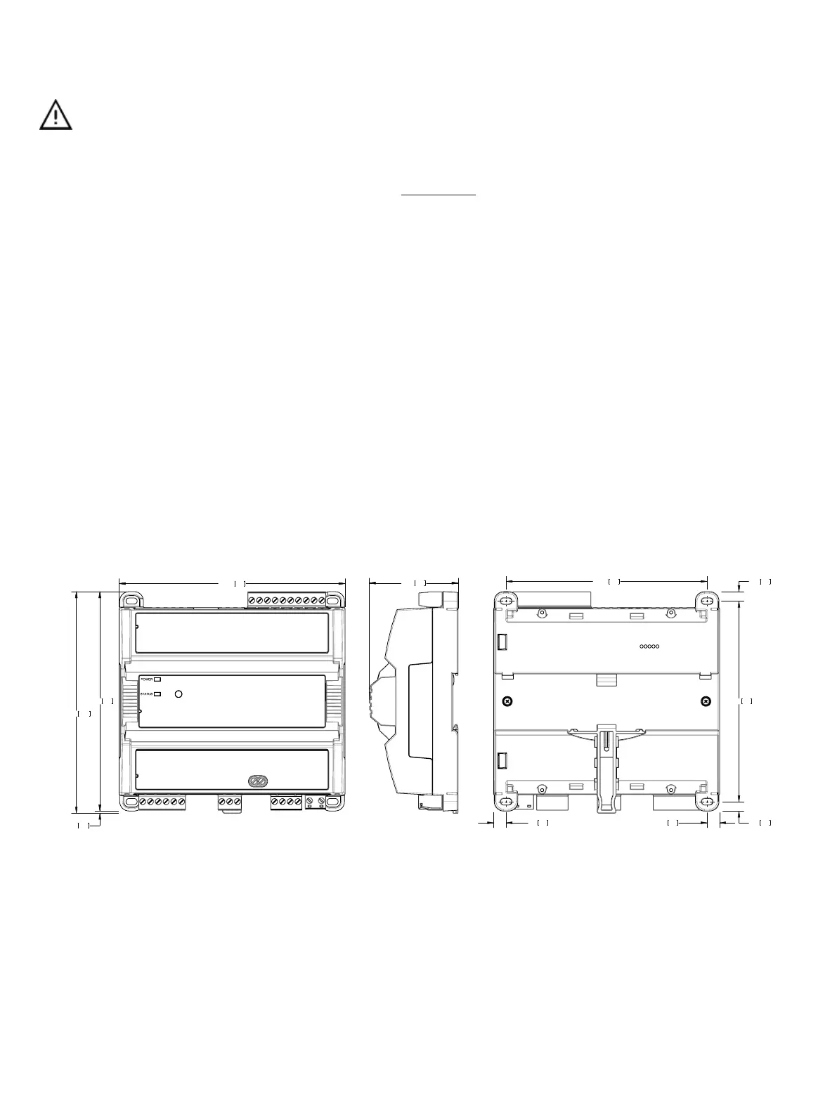
Module Enclosure Dimensions
5.71145.00
5.54
140.84
5.60142.22
Front
2.2456.88
Profile
Millimeters [Inches]
0.246.04
5.07
128.76
0.246.04
5.08129.01
0.317.990.317.99
Back
0.051.38
Figure1: Dimensions without terminal covers