8 / 15
Output Wiring
Output options must be properly configured in EC-
gfx
Program to ensure correct output values. The table below shows the available output wiring meth-
ods. Outputs can be connected as follows.
Before connecting an output device (actuator, relay, etc.) to the controller, refer to the datasheet and installation
guide of the equipment manufacturer.
£ For a wire length less than 10’ (3m) long, either a shielded or unshielded 18AWG wire may be used.
£ For a wire length up to 33’ (10m) long, a shielded 18AWG wire is recommended.
£ The shield of the wire should be grounded on the controller side and the shield connection to the ground
should be kept as short as possible.
£ For relay and triac outputs; select appropriately-sized wiring suitable to the current load.
Relay Contact Outputs
The relay contact outputs (DO1, DO2 & DO3) can switch up to 3 A (inductive / resistive - total of all fan relay contact outputs) for fan speed control.
£ Fan relay contacts are unpowered and an external power supply is required (max 277VAC).
£ The fan relay contact outputs are normally open.
£ All fan relay contact output connectors accept wires between 1 mm² (17 AWG) and 1.5 mm² (16 AWG). Select proper gauge according to the cur-
rent load.
£ It is recommended to use an appropriate external protection when connected to a highly inductive load.
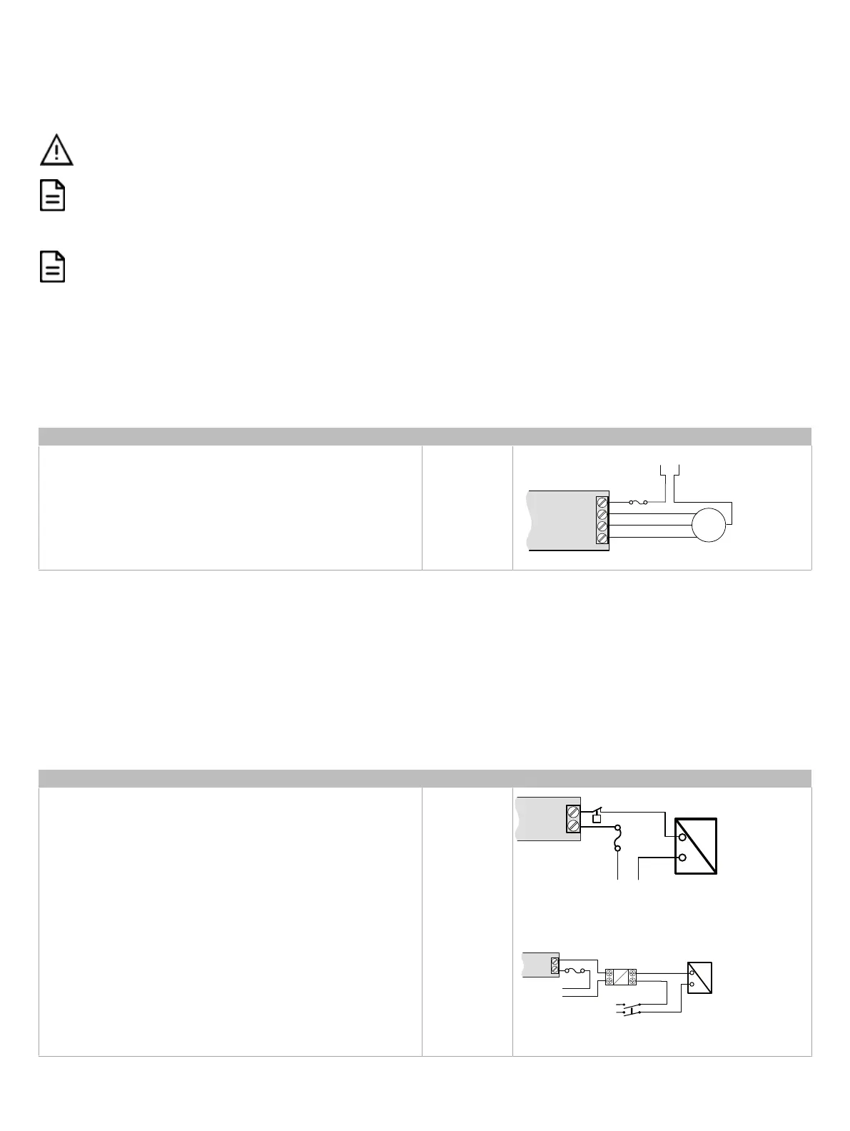
Description Designation Connection Diagram
Fan speed DO1-DO2-DO3
DO
1DO
3
DO2
Un
M
3
2
1
Line-
to-Neutral AC Power Source
NeutralLine
3 A Fuse
Fan
Electric Heater
The relay contact output (DO4-C4) can switch up to 9 A (resistive) for electric heater control up to 277 VAC. For example, this output can handle electric
heaters up to 2 kW @ 230 VAC.
£ If more power is needed, a relay must be connected to the relay contact output.
£ The heater relay outputs are unpowered. You must use the same Live conductor (power source) to power the heater as the one used to power the
controller.
£ All digital relay contact outputs are normally open.
£ All relay contact output connectors accept wires between 1.5 mm² (16 AWG) and 2.5 mm² (14 AWG). Select proper gauge according to the current
load.
£ It is recommended to use an appropriate external protection when connected to a highly inductive load.
£ It is recommended to use a 10 A fast-acting, high-breaking fuse to protect the heater relay contact output against short circuit/overload conditions.
Description Designation Connection Diagram
Electric heat DO4-C4
Cx
DOx
Fuse
Electric Heater
Safety Thermostat
Electric Heater
Power Supply
(same live conductor
as the controller)
Relay Contact outputs - Electric Heater (I
Electric Heater
< I
Max
)
L
N
DOx
Cx
A2
A1
L
N
Polarization
Voltage
s
(same live conductor
as the controller)
Fuse
Relay
Electric Heater
2-Line Main
Power Disconnect
Electric Heater
Power Supply
Relay Contact outputs - Electric Heater (I
Electric Heater
> I
Max
)