9 / 15
Triac Outputs
Triac outputs can be used to turn equipment and devices on and off (two-state outputs) and to control valve and damper actuators using Pulse Width
Modulation (PWM).
£ Triac output: 24 VAC (Max: 600 mA)
£ To measure the state of a triac output, an external load must be connected.
£ Triac output connectors accept wires between 1 mm² (17 AWG) and 1.5 mm² (16 AWG). Make sure the wires are suitable for the connected loads.
£ If functional Earth is connected, triac output circuits will be PELV.
£ If functional Earth is NOT connected, triac output circuits will be SELV.
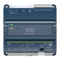
Description Designation Connection Diagram
Thermal Valve DO5-DO6
Proportional valve: requires two Triac outputs DO5-DO6
DOx
DOx
COM
Proportional Valve
Analog Outputs
Analog outputs are configured to provide a linear signal ranging from 0 to 10 VDC.
£ Analog output connectors accept wires between 0.75 mm² (18 AWG) and 1.5 mm² (16 AWG).
£ If an analog actuator is being controlled, connect the 0 to 10 VDC output, along with an external 24 VAC power source, to the analog actuator.
£ The onboard 24 VAC power supply can be used to power 0-10 V actuators.
£ If functional Earth is connected, analog output circuits will be PELV.
£ If functional Earth is NOT connected, analog circuits will be SELV.
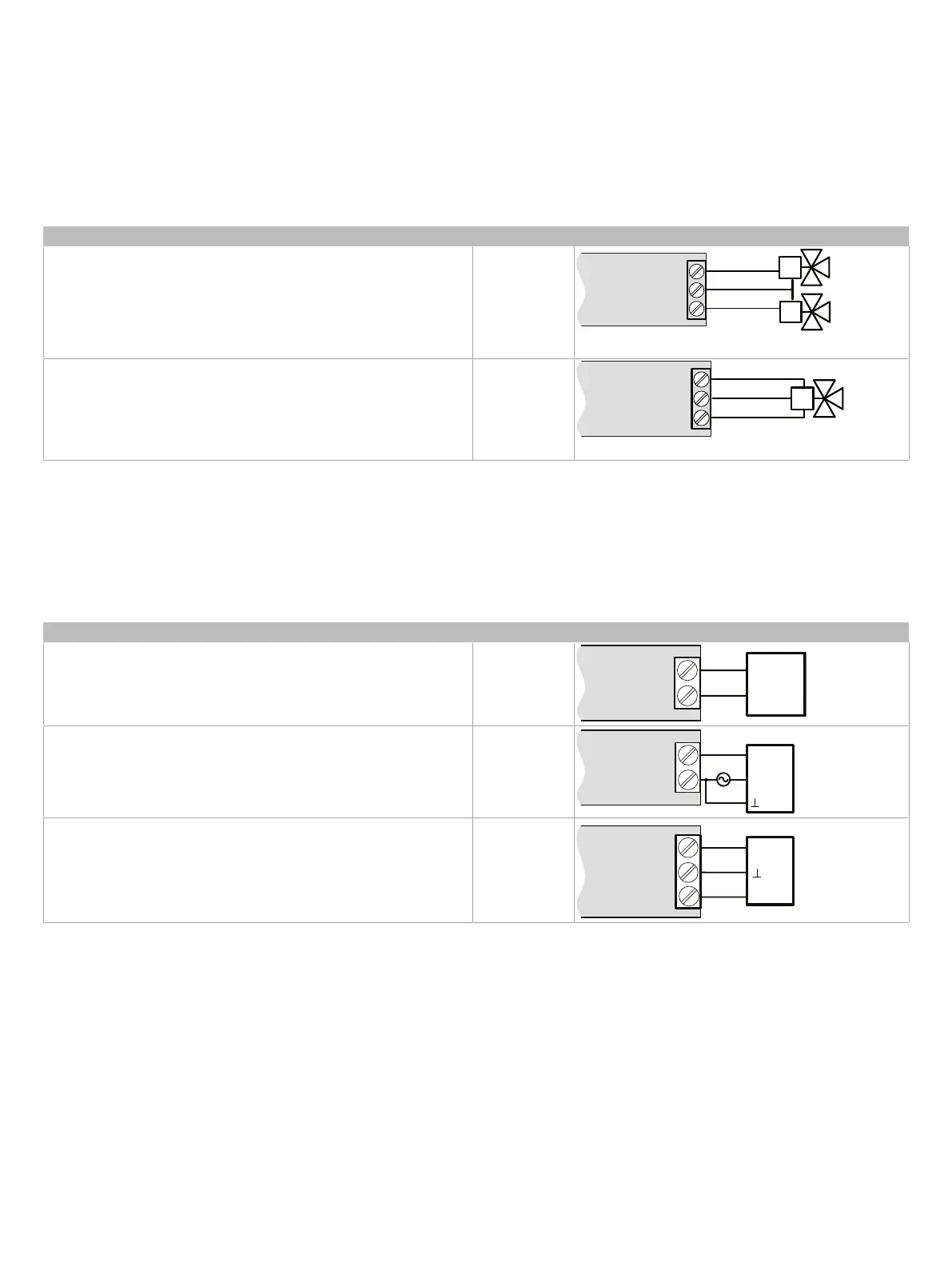
Control Output Type Designation Connection Diagram
0 to 10VDC voltage output AOx
0 to 10VDC voltage output controlling an analog actuator powered by an
external 24VAC power source
AOx
AOx
COM
0
-
10
V
~
or
+
Actuator
or
-
24
VAC
0 to 10VDC voltage output controlling an analog actuator powered by the
controller
AOx
AOx
COM
0-
10
V
~
or +
Actuator
or -
24V~